This RGB LED interfacing with MSP430G2 LaunchPad tutorial shows you how to wire a three-color RGB LED to the MSP430G2553 microcontroller and control it from the Energia IDE. An RGB LED is a single LED package that combines red, green, and blue emitters. By mixing these three primary colors at different intensities, you can produce any color of the visible spectrum — white, yellow, cyan, magenta, purple, orange, and so on. This makes RGB LEDs ideal for status indicators, mood lighting, notification LEDs, and visual effects in embedded projects, because a single component can replace three separate single-color LEDs.
In this guide we connect each of the LED’s three color pins to a GPIO pin on the MSP430G2 LaunchPad and cycle through red, green, and blue one second at a time. Along the way you will learn the difference between common-anode and common-cathode RGB LEDs, why current-limiting resistors are mandatory, and the simple setColor() pattern you can use to drive any color from code.
Before continuing, it helps to have completed the first two tutorials in this MSP430G2 series, which walk through Energia IDE setup and GPIO basics:
- MSP430G2 LaunchPad Getting Started Tutorial with Energia IDE
- MSP430G2 LaunchPad GPIO Tutorial – Input/Output Pins
Recommended Components
The following components are used in this project or are helpful for getting started with MSP430 LaunchPad development.
| Component | How it’s used in this project | Buy on Amazon |
|---|---|---|
| MSP430G2 LaunchPad | The MSP-EXP430G2 LaunchPad (MSP430G2553) used in this project. | Check Price |
| Mini-USB Cable | Type-A to Mini-B cable to program and power the LaunchPad over USB. | Check Price |
| RGB LED | 4-pin common-cathode RGB LED driven on three GPIO pins. | Check Price |
| Resistor Kit (220Ω) | Current-limiting resistors, one per color pin for each emitter. | Check Price |
| Breadboard | Solderless breadboard to build the RGB LED circuit. | Check Price |
| Jumper Wires | Connect each color pin and the common pin to the LaunchPad. | Check Price |
As an Amazon Associate we earn from qualifying purchases. Prices and availability are accurate as of the date/time indicated and are subject to change.
What You Will Learn
- What an RGB LED is and how three color emitters in one package produce a full color spectrum
- The difference between common-anode and common-cathode RGB LEDs and how that affects wiring
- Why current-limiting resistors are mandatory on every color pin (and how to pick the right value)
- Which MSP430G2 LaunchPad header pins to use for red, green, and blue
- A complete circuit diagram for RGB LED interfacing with the MSP430G2553
- A clean
setColor(r, g, b)function pattern for driving any color from code - How to extend the example to produce full-color mixing with PWM (link to the PWM tutorial)
- Common RGB LED troubleshooting: wrong polarity, dim colors, stuck on one color
Prerequisites and Required Components
- MSP430G2 LaunchPad (MSP430G2553)
- 1 × RGB LED (4-pin, common-cathode — the most common type in beginner kits)
- 3 × 330 Ω resistors — one per color pin (or use a pre-built RGB LED module that has resistors on board)
- Breadboard and jumper wires
- Energia IDE installed and configured
- Basic understanding of GPIO output (see the prerequisite tutorials above)
Introduction to RGB LEDs
An RGB LED is a light-emitting diode that can produce any color you want, on demand, under software control. Internally, it is three discrete LED dies — one red, one green, one blue — housed together inside a single clear package. By turning each of the three emitters on or off (or, using PWM, driving them at varying brightness), you mix the three primary colors additively to produce every other color in the visible spectrum. For example, red + green = yellow; red + blue = magenta; all three at equal intensity = white.
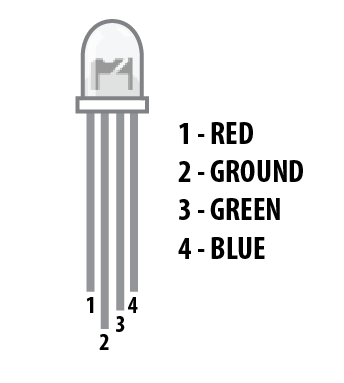
Unlike a regular LED that has only two pins, an RGB LED has four pins: one for each color emitter (red, green, blue) plus one common pin. The longest pin is the common terminal — either the common cathode (connected to GND) or the common anode (connected to +V) depending on the type. Knowing which type you have is critical, because the wiring and the code logic both flip between the two.
Common Anode vs Common Cathode RGB LED
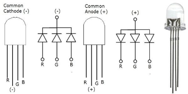
- Common cathode RGB LED: the long pin is the shared cathode and connects to GND. Each color pin is an anode — drive it HIGH from the MSP430 to light that color. HIGH = ON.
- Common anode RGB LED: the long pin is the shared anode and connects to 3.3 V on the LaunchPad. Each color pin is a cathode — drive it LOW from the MSP430 to light that color. LOW = ON (inverted logic).
In this tutorial we use a common-cathode RGB LED, so the long leg connects to GND. If you only have a common-anode version, connect the long leg to 3.3 V instead (not 5 V — the MSP430 is a 3.3 V part) and invert the HIGH/LOW values in the code.
Do not connect the common anode pin to 5 V when using an MSP430G2 LaunchPad. The MSP430 is a 3.3 V part and its GPIO pins are not 5 V tolerant — mixing 5 V and 3.3 V domains through the LED can damage the microcontroller.
How to Interface an RGB LED with the MSP430G2 LaunchPad
Let’s connect the RGB LED to the MSP430G2 LaunchPad. Each color emitter inside the RGB LED is a real LED and, like any LED, it needs a current-limiting resistor in series. Without a resistor — or with a resistor that’s too small — the LED draws too much current and will burn out, and the MSP430 pin can be stressed beyond its ~6 mA safe limit.
A 330 Ω resistor is the standard choice for each color pin at 3.3 V. Higher values (like 470 Ω or 1 kΩ) give a dimmer LED but are safer for the MSP430; lower values give a brighter LED at the cost of pin current. If you buy a pre-assembled RGB LED module for breadboards, the module already includes the three resistors on the PCB, so you can connect directly.
RGB LED Circuit Diagram

Wire the circuit according to the diagram above. Connect each color pin of the common-cathode RGB LED to an MSP430 GPIO pin through a 330 Ω resistor, and connect the long common pin directly to GND. If you are using a breadboard RGB LED module, the resistors are already on board — just wire each color pin straight to the LaunchPad. The pin assignments used in this tutorial are:
- Red pin → MSP430G2 LaunchPad header pin 13 (P2.5)
- Green pin → MSP430G2 LaunchPad header pin 14 (P1.6)
- Blue pin → MSP430G2 LaunchPad header pin 15 (P1.7)
- Common pin (long leg) → GND
RGB LED Code for MSP430G2 LaunchPad
The following Energia sketch cycles the RGB LED through red, green, and blue — each color on for one second, then the next. It introduces a small helper function, setColor(), which takes three arguments (r, g, b) and writes each to the corresponding GPIO pin. This pattern is the clean way to control an RGB LED: the main loop just calls setColor(1, 0, 0) for red, setColor(0, 1, 0) for green, and so on, without having to repeat three digitalWrite() calls every time.
int redPin   = 13;   // header pin 13 (P2.5) → red
int greenPin = 14;   // header pin 14 (P1.6) → green
int bluePin  = 15;   // header pin 15 (P1.7) → blue

void setup() {
  pinMode(redPin,   OUTPUT);
  pinMode(greenPin, OUTPUT);
  pinMode(bluePin,  OUTPUT);
}

void loop() {
  setColor(1, 0, 0);  // Red
  delay(1000);
  setColor(0, 1, 0);  // Green
  delay(1000);
  setColor(0, 0, 1);  // Blue
  delay(1000);
}

// Helper: drive each color channel HIGH or LOW.
// For common-cathode LEDs: 1 = ON, 0 = OFF.
// For common-anode LEDs: invert these values (1 = OFF, 0 = ON).
void setColor(int redValue, int greenValue, int blueValue) {
  digitalWrite(redPin,   redValue);
  digitalWrite(greenPin, greenValue);
  digitalWrite(bluePin,  blueValue);
}
How the RGB LED Code Works
The first three lines give human-friendly names to the three header pin numbers. Inside setup(), all three pins are configured as digital outputs with pinMode() — this only runs once, when the MSP430 resets. Inside loop(), the sketch calls setColor() three times with different arguments to select red, green, and blue in turn. The delay(1000) between each call holds each color on for one second.
Upload the code to the MSP430G2 LaunchPad. The RGB LED starts cycling — red for one second, then green, then blue, and loops forever. This confirms that all three color channels are wired correctly and the MSP430 is driving each one independently.
Mixing Colors with the RGB LED (PWM Upgrade)
The code above only gives you the three pure primary colors because digitalWrite() is binary — the pin is either fully ON (HIGH) or fully OFF (LOW). To produce secondary colors like yellow, cyan, or white (and smooth color fades), you need to control the brightness of each channel independently. This is done with Pulse Width Modulation (PWM), which rapidly switches the pin on and off at a duty cycle proportional to the desired brightness.
Energia exposes PWM through the analogWrite(pin, value) function, where value is 0–255 (0 = off, 255 = full brightness). The updated setColor() helper looks like this:
void setColor(int redValue, int greenValue, int blueValue) {
  analogWrite(redPin,   redValue);
  analogWrite(greenPin, greenValue);
  analogWrite(bluePin,  blueValue);
}

// Usage examples:
// setColor(255, 0, 0);    // pure red
// setColor(255, 255, 0);  // yellow
// setColor(128, 0, 128);  // purple
// setColor(255, 255, 255);// white
For a deeper dive into how PWM works on the MSP430, see our dedicated tutorial: Pulse Width Modulation using MSP430 LaunchPad. Note that only certain pins on the MSP430G2 LaunchPad support hardware PWM — refer to the PWM tutorial for the exact list.
Troubleshooting RGB LED Issues
- No color lights up. Either the long leg isn’t connected to GND (common cathode) or the resistors are on the wrong side of the LED. Check polarity and verify each color pin reads 3.3 V with a multimeter when the corresponding
digitalWrite()is HIGH. - Only one or two colors work. Likely a wiring mistake on the non-working color pin, or the color emitter itself is dead (rare but possible on cheap LEDs). Swap the color pin to a known-working header pin to isolate the problem.
- All colors appear very dim. The resistor values are too high (try 220 Ω), or the common leg is not properly grounded. Measure the voltage across the resistor — if it’s close to 3.3 V, the LED isn’t conducting.
- Colors are inverted (LED is on when code says off). You have a common-anode LED wired as if it were common-cathode. Either flip the wiring (long leg to 3.3 V, not GND) or invert the logic in
setColor()(HIGH → LOW,LOW → HIGH). - Colors are there but the mix looks wrong (e.g., white looks pink). Normal — red, green, and blue emitters inside most cheap RGB LEDs have different forward voltages and luminous efficiencies, so equal PWM values don’t give a perfectly neutral white. Tune the PWM values experimentally, or use higher-quality LEDs.
- MSP430 gets warm. The resistors are too small and the LED is drawing more than 6 mA per color channel. Increase resistor values or use a driver transistor.
Frequently Asked Questions
How do I know if my RGB LED is common anode or common cathode?
Check the datasheet of the RGB LED package — it will explicitly say “common anode” or “common cathode.” If you don’t have the datasheet, wire the long leg to 3.3 V through a 330 Ω resistor and touch each short leg to GND one by one. If any color lights up when its pin goes to GND, it’s common anode. If nothing lights up, flip it: long leg to GND, short legs to 3.3 V through the resistor — if colors light that way, it’s common cathode.
Do I need separate resistors for each color or one resistor on the common pin?
Always use one resistor per color pin. A single resistor on the common leg would share current across all three emitters, but each color has a different forward voltage (red ~1.8 V, green ~3.0 V, blue ~3.2 V) — so the current would be unbalanced and the colors wouldn’t mix predictably. Three separate 330 Ω resistors give you clean, consistent color control.
Can I use any GPIO pin on the MSP430G2 LaunchPad for RGB LED control?
For simple on/off control (digitalWrite), any GPIO pin works. For smooth color mixing with PWM (analogWrite), you need a pin that supports hardware PWM on the MSP430G2553 — common PWM-capable pins are header pins 9 (P2.1), 10 (P2.2), 14 (P1.6), and 19 (P2.7). See the PWM tutorial for the complete list.
What resistor value should I use for RGB LEDs?
330 Ω is the standard default for a 3.3 V supply — it keeps current well below the MSP430’s 6 mA per-pin limit while giving reasonable brightness. 470 Ω gives a dimmer, safer result; 220 Ω gives a brighter LED but pushes close to the pin’s current limit. Never go below 220 Ω on an MSP430 circuit.
Can I control WS2812 / NeoPixel RGB LEDs with the MSP430G2?
Yes, but it requires a different approach. WS2812 LEDs use a fast serial protocol (~800 kHz bit timing), not simple GPIO. There are Energia libraries that implement the WS2812 protocol for the MSP430G2553, though the 16 MHz clock and 512 bytes of RAM put tight limits on how many pixels you can drive. For more than a handful of pixels, consider a higher-spec chip like the MSP432 or an ESP32.
Why is my RGB LED white not pure white?
Because the three emitters inside a cheap RGB LED have different brightness characteristics. Simply setting all three to full brightness (analogWrite(pin, 255)) usually produces a bluish or greenish “white” because the blue and green emitters out-shine the red. Tune the PWM values experimentally — for example, setColor(255, 180, 160) often produces a much more neutral white.
Conclusion
You have now successfully interfaced an RGB LED with the MSP430G2 LaunchPad using just three GPIO pins, three resistors, and a handful of lines of Energia code. You learned the difference between common-anode and common-cathode RGB LEDs, the critical role of the current-limiting resistor, and a clean setColor() function pattern you can reuse in any future project. The next step is to upgrade digitalWrite() to analogWrite() with PWM so you can produce the full range of colors, fades, and effects — covered in the PWM tutorial linked below.
Related MSP430G2 LaunchPad Tutorials
- MSP430G2 LaunchPad Getting Started Tutorial with Energia IDE
- MSP430G2 LaunchPad GPIO Tutorial – Input/Output Pins
- Motion Sensor Interfacing with MSP430G2 LaunchPad
- LCD Interfacing with MSP430 LaunchPad
- Pulse Width Modulation using MSP430 LaunchPad – Control LED Brightness
- How to Use ADC of MSP430 Microcontroller
- UART Serial Communication with MSP430 Microcontroller