In this tutorial, we will learn to configure a DAC module of STM32F4 discovery with HAL DAC drivers and Keil uvision IDE. Moreover, we will learn to configure the STM32F4 DAC module manually without DMA and any trigger conversion event such as timers. We will learn to use DAC in DMA mode with a timer as a trigger conversion source in the coming articles.
STM32F4 DAC Introduction
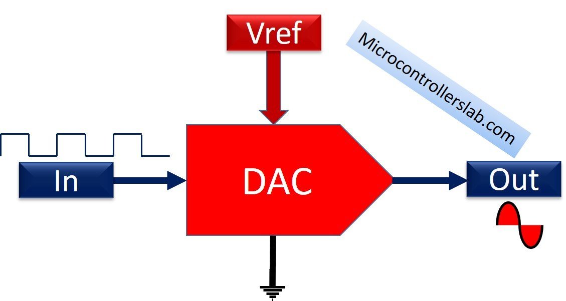
A Digital to analog converter is a device that converts a constant number into an analog value. Unlike ADC, a DAC produces an analog signal from a digital value. The output of a digital value depends on the Vref and digital value input to a DAC module. As you can see in this block diagram, the input signal to this converter is a digital signal and a reference voltage with respect to the ground terminal. The output is an analog signal.

The DAC modules of STM32F4 are R-2R ladder based. Hence, the following equation is used to calculate an analog output from a numeric value (D). Here N is a width of DAC which in the case of STM32F407VG microcontroller is 12-bit.
Vout = (Vref x D) / 2^N
You can refer to this article to find more about digital to analog converters and their types:
DAC Module STM32F4
STM32F4 discovery board development board comes with an STM32F407VG microcontroller. This microcontroller has two 12-bit digital to analog converters such as DAC1 and DAC2. Both these DACs can be used independently or concurrently for dual-mode.
DAC Output Pins
Now the next question is through which GPIO pins digital to analog converter produces output? Suppose you examine the STM32F4 discovery board’s datasheet and refers to table 7 in the pinout and pin description section. In that case, you will notice that PA4 and PA5 pins provide additional functionality for DAC1 and DAC2 channel output, respectively.
The output of DAC channel
- DAC channel1 with DAC_OUT1 (PA4) as output
- DAC channel2 with DAC_OUT2 (PA5) as output
Getting Analog Output from Digital Input Signal
As discussed in the last section, this equation is used to obtain analog voltage output from a digital numeric input value:
Vout = (Vref x D) / 2^N
The reference voltage is usually the operating voltage of the microcontroller with reference to the ground terminal. The operating voltage of STM32F4 disovery board is 3.3V. Hence, Vref will be 3.3V.
Note: The output voltage value depends on the Vref voltage. The analog output signal will be between 0-3.3V ( Maximum = Vref).
The DAC module of STM324F microcontroller is of 12-bit. But it is programmable to configure in 6-bit, 8-bit, 10-bit and 12-bit mode. For example, we are using a 12-bit DAC. Let’s see the analog output voltage value for a constant value of 1000.
For 12-bit DAC = 2^12 = 4096
Vout = (Vref x D) / 2^N = (3.3 x 1000)/4096 = 0.806V
The numeric value (D) can be any value between 0 and 4095. Hence, the output voltage will be between the minium value 0 ( D =0 ) and the maximum value 3.29V (D=4095).
STM32F4 DAC Accuracy and Minimum step voltage
The accuracy and the minimum step output voltage of a DAC module depend on the reference voltage and size of a DAC. For example, we take 12-bit DAC and Vref equal to an operating voltage of the STM32F4 discovery board. Then the minimum step voltage will be:
Minimum Step Voltage= (Vref x D) / 2^N = (3.3 x 1)/4096 = 0.8mV
HAL DAC Driver STM32F4
After understanding digital to analog converters and their working, now let’s move to the programming part of STM32F4 DAC modules. In this section,we will discuss HAL DAC library of STM32F407VG microcontroller.
To use the HAL DAC driver, HAL provides two important C structures such as DAC_HandleTypeDef and DAC_ChannelConfTypeDef.
Let’s first discuss DAC_HandleTypeDef C struct. This structure is used to configure and manipulate the DAC peripheral of STM32F4.
typedef struct
{
  DAC_TypeDef     *Instance;     /*Pointer to DAC base address discriptor  */
__IO HAL_DAC_StateTypeDef   State;     /*DAC communication state */
  HAL_LockTypeDef     Lock;          /* DAC locking object */
  DMA_HandleTypeDef     *DMA_Handle1;  /*Pointer to DMA handler for channel 1 */
  DMA_HandleTypeDef    *DMA_Handle2;  /*!< Pointer to DMA handler for channel 2 */
  __IO uint32_t         ErrorCode;     /*< DAC Error code*/
}DAC_HandleTypeDef;
Now let’s discuss members of this C struct which we will use in this tutorial. The remaining members will be discussed in the later tutorial.
Instance : It is a pointer to the DAC module that we want to use. For example, if we want to use DAC2 or DAC1, we will pass DAC to this member.
DAC Channel and Trigger Event Selection
The second important C struct for DAC configuration and channel selection is DAC_ChannelConfTypeDef.
typedef struct
{
uint32_t DAC_Trigger; /*Selects the external trigger for the selected DAC channel.
 */
uint32_t DAC_OutputBuffer;  /*Specifies whether the DAC channel output buffer is enabled or disabled. */
}DAC_ChannelConfTypeDef;
DAC_Trigger: This member selects the source of trigger for DAC conversion. In STM32F4, the source of trigger for DAC can be manual, DAM, external, or timer trigger. For example, if we set the DAC_Trigger to DAC_TRIGGER_NONE, the DAC conversion will be done manually by using HAL_DAC_SetValue() function. We will discuss it later.
The value of different DAC Trigger selection options are listed in this table:
| Value | Function |
|---|---|
| DAC_TRIGGER_NONE | Conversion is automatic and not by external any trigger ( manual) |
| DAC_TRIGGER_T2_TRGO | TIM2 TRGO selected as external conversion trigger for DAC channel |
| DAC_TRIGGER_T4_TRGO | TIM4 TRGO selected as external conversion trigger for DAC channel |
| DAC_TRIGGER_T5_TRGO | TIM5 TRGO selected as external conversion trigger for DAC channel |
| DAC_TRIGGER_T6_TRGO | TIM6 TRGO selected as external conversion trigger for DAC channel |
| DAC_TRIGGER_T7_TRGO | TIM7 TRGO selected as external conversion trigger for DAC channel |
| DAC_TRIGGER_T8_TRGO | TIM8 TRGO selected as external conversion trigger for DAC channel |
| DAC_TRIGGER_EXT_IT9 | EXTI Line9 event selected as external conversion trigger for DAC channel |
| DAC_TRIGGER_SOFTWARE | Conversion started by software trigger for DAC channel |
DAC_OutputBuffer: Enables or disables the DAC output buffer.
| Value | Functions |
|---|---|
| DAC_OUTPUTBUFFER_ENABLE | Enable DAC Buffer |
| DAC_OUTPUTBUFFER_DISABLE | Disable DAC Buffer |
DAC Initialization and Configuration Functions
Two Functions are used to configure and initialize DAC with the help of above-defined C structs such as HAL_DAC_Init() and HAL_DAC_ConfigChannel().
HAL_StatusTypeDef HAL_DAC_Init(DAC_HandleTypeDef* hdac)The input argument to HAL_DAC_Init() function is a instance to the pointer of struct DAC_HandleTypeDef and return type is HAL_StatusTypeDef which is initialized in this enum struct:
typedef enum
{
  HAL_OK       = 0x00U,
  HAL_ERROR    = 0x01U,
  HAL_BUSY     = 0x02U,
  HAL_TIMEOUT  = 0x03U
} HAL_StatusTypeDef;
HAL_StatusTypeDef HAL_DAC_ConfigChannel(DAC_HandleTypeDef* hdac, DAC_ChannelConfTypeDef* sConfig, uint32_t Channel)HAL_DAC_ConfigChannel() functions initialize the selected ADC channel. The first two input argument to this function are pointers to the instance of DAC_HandleTypeDef and DAC_ChannelConfTypeDef structs, respectively. The third input argument is a DAC channel number. We can select on of these two values depending on channel that we want to use.
| Value | Function |
|---|---|
| DAC_CHANNEL_1 | Selects DAC channel 1 |
| DAC_CHANNEL_2 | Select DAC channel 2 |
As we mentioned earlier, the DAC module can be used manually without any trigger source. In this tutorial, we will learn to use it manually without any trigger source. These three functions are used to start, stop, set value of STM32F4 DAC in DAC_TRIGGER_NONE mode.
DAC Conversion Function
After initialization and configuration of DAC is to start the DAC conversion by using HAL_DAC_Start(). The input argument to HAL_DAC_Start() function is an instance to the pointer of struct DAC_HandleTypeDef and the return type is HAL_StatusTypeDef enum which is given above. A second argument is a channel number. Similarly, we can stop the conversion by calling HAL_DAC_Stop().
HAL_StatusTypeDef HAL_DAC_Start(DAC_HandleTypeDef* hdac, uint32_t Channel);
HAL_StatusTypeDef HAL_DAC_Stop(DAC_HandleTypeDef* hdac, uint32_t Channel);
After DAC starts conversion by calling HAL_DAC_Start() function, we can set the value of DAC by passing numeric value to HAL_DAC_Start() function.
HAL_StatusTypeDef HAL_DAC_SetValue(DAC_HandleTypeDef* hdac, uint32_t Channel, uint32_t Alignment, uint32_t Data);
Here the first two arguments are a pointer to the instance of DAC_HandleTypeDef and the channel number, respectively. The third input argument is a data allignment parameter the value which should be selected according to DAC width.
#define DAC_ALIGN_12B_R                    0x00000000U
#define DAC_ALIGN_12B_L                    0x00000004U
#define DAC_ALIGN_8B_R                     0x00000008U
The fourth input argument is a numeric value against which we want to a analog output value.
In the end, we should also configure the corresponding output pin of DAC as an analog output pin. If you don’t know how to use GPIO pins of the STM32F4 discovery board, you can refer to these articles:
- LED Blinking Tutorial STM32F4 Discovery Board
- Use Push Button to Control LEDs of STM32F4 Discovery Board
- ADC STM32F4 Discovery Board
STM32F4 DAC Example Code
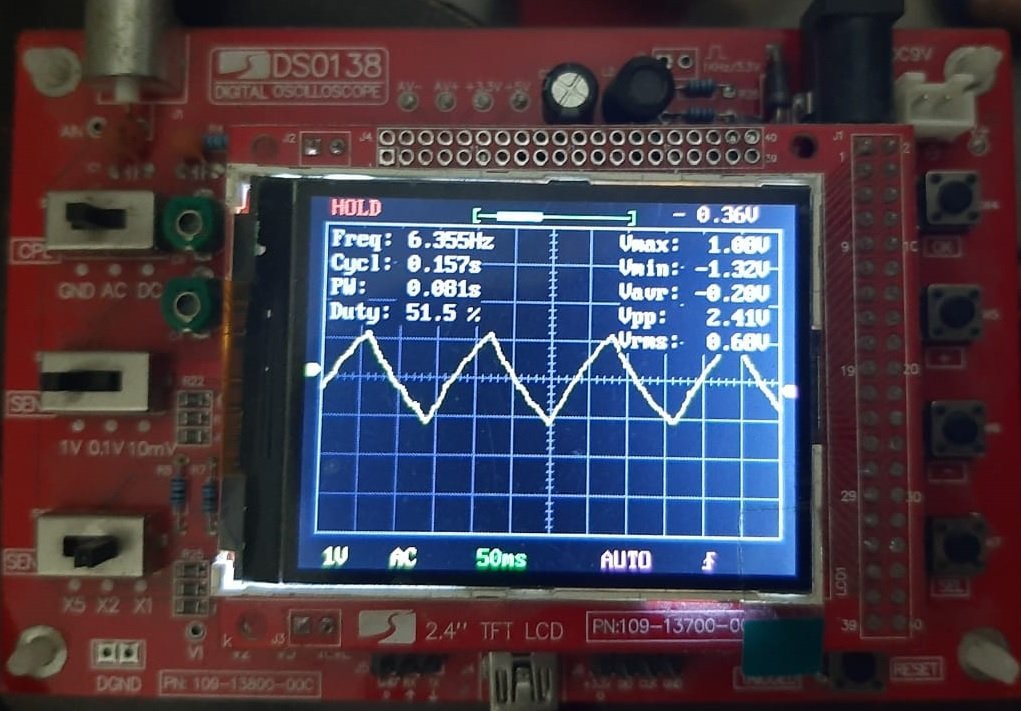
The following example code generates an analog output signal on the PA5 pin of the STM32F4 discovery board. It will produce a triangle waveform on the PA5 pin. Because we pass the numeric values to HAL_DAC_SetValue() function first in increasing order from low to the maximum value. After that, we pass the values from the highest value to the minimum value using two for loops.
/*Include header file for STM32F4 HAL libraries and callback functions */
#include "stm32f4xx_hal.h"

/* Function prototype to configure and initialize DAC and GPIO pin */
void configure_DAC(void);
void configure_GPIO(void);
void Delay_ms(volatile int time_ms);
/* create an instance to DAC_HandleTypeDef C struct */
DAC_HandleTypeDef DAC_Config;


/* main function to set DAC numeric value */
int main(void)
{
configure_DAC(); // call DAC initialization and configuration routine
configure_GPIO(); // call GPIO PA5 initialization and configuration routine

/* Start DAC conversion with DAC_CHANNEL_2 */
HAL_DAC_Start(&DAC_Config, DAC_CHANNEL_2);
while(1)
{
	int D_Value = 1;
 while(D_Value < 4000) {
 HAL_DAC_SetValue(&DAC_Config, DAC_CHANNEL_2, DAC_ALIGN_12B_R, D_Value);
 Delay_ms(1);
 D_Value+=100;
 }

 while(D_Value > 1) {
 HAL_DAC_SetValue(&DAC_Config, DAC_CHANNEL_2, DAC_ALIGN_12B_R, D_Value);
 Delay_ms(1);
 D_Value-=100;
 }
 }
}

/* Initialize and configure DAC_Channel_2 */
void configure_DAC(void)
{
 DAC_ChannelConfTypeDef Channel_Config;
 __HAL_RCC_DAC_CLK_ENABLE();
 /* DAC Initialization */
 DAC_Config.Instance = DAC;
 HAL_DAC_Init(&DAC_Config);

 /* DAC channel_OUT2 config */
 Channel_Config.DAC_Trigger = DAC_TRIGGER_NONE;
 Channel_Config.DAC_OutputBuffer = DAC_OUTPUTBUFFER_ENABLE;
 HAL_DAC_ConfigChannel(&DAC_Config, &Channel_Config, DAC_CHANNEL_2);
}
/* Initialize and configure GPIO PA4 as a analog pin */
void configure_GPIO(void)
{

/* DAC GPIO ---> PA5 */
 GPIO_InitTypeDef GPIO_InitStruct;
 GPIO_InitStruct.Pin = GPIO_PIN_5;
 GPIO_InitStruct.Mode = GPIO_MODE_ANALOG;
 GPIO_InitStruct.Pull = GPIO_NOPULL;
 HAL_GPIO_Init(GPIOA, &GPIO_InitStruct);
}
/*Generate ms */
void Delay_ms(volatile int time_ms)
{
	      int j;
        for(j = 0; j < time_ms*4000; j++)
            {}  /* excute NOP for 1ms */
}
DAC Example Code Output

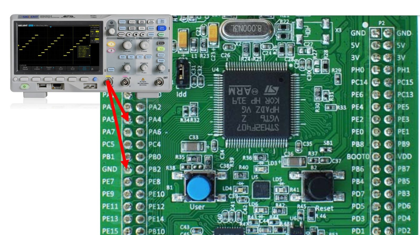
Now to see the output of the above code, connect one terminal of an oscilloscope with the PA5 pin of the STM32F4 discovery board and the ground terminal with the ground pin of the discovery board. You will get a sawtooth trianglular on the oscilloscope screen.

How Code Works?
To generate a triangular waveform, we provide numeric values to the DAC module in increasing and decreasing order, respectively. First while loop, set numeric values in increasing order from 1 to 4000 with each increment of 100. But as soon as D_value reaches 4000 first while loop terminates and the second while loop starts to execute.
int D_Value = 1;
 while(D_Value < 4000) {
 HAL_DAC_SetValue(&DAC_Config, DAC_CHANNEL_2, DAC_ALIGN_12B_R, D_Value);
 Delay_ms(1);
 D_Value+=100;
 }
In the second while loop, we provide numeric value to the DAC module in decreasing order starting from 3900 with each decrement of 100. But as soon as D_value reaches 100, the second while loop terminates and the start execution from while(1) again. This pattern keeps executing.
 while(D_Value > 1) {
 HAL_DAC_SetValue(&DAC_Config, DAC_CHANNEL_2, DAC_ALIGN_12B_R, D_Value);
 Delay_ms(1);
 D_Value-=100;
 }
In the coming tutorials, we will see how to use DAC module of STM32F4 with DMA and timers as DAC trigger source.
Related Tutorials:

The code in this article is incomplete and does not compile.
You need to include the complete source listing.