This tutorial is about how to use FreeRTOS structured queue to receive data from multiple resources. In the last tutorial, we have learned to use message queues with FreeRTOS API and Arduino. But in that example, we used a single queue to receive and send data from single tasks. But in real-time operating systems, it is also possible that a single task receives data from multiple resources by using a single queue. However, the multiple sender tasks can write data to a single queue, but the issue is that the receive task should know from which task data came from.
If you are just starting with FreeRTOS with Arduino, you can read this getting started guide:
How to use FreeRTOS with Arduino
Recommended Components
The following are recommended for following along with these FreeRTOS Arduino tutorials.
| Component | How it’s used in this project | Buy on Amazon |
|---|---|---|
| Arduino Starter Kit (Uno R3) | An Arduino board and parts to build and run the FreeRTOS example tasks. | Check Price |
| 37-in-1 Sensor Modules Kit | Assorted sensor modules handy for the FreeRTOS tasks, queues and semaphore demos. | Check Price |
| Hands-On RTOS with Microcontrollers (Book) | Recommended reference for learning FreeRTOS concepts in depth. | Check Price |
| Hands-On RTOS with Microcontrollers (2nd Edition) | Updated second edition of the FreeRTOS reference book. | Check Price |
As an Amazon Associate we earn from qualifying purchases. Prices and availability are accurate as of the date/time indicated and are subject to change.
Why do we used queues Structure?
Why is it necessary for the receiver task to the know the source of data?
Because otherwise there is no other way, the receiver can differentiate data resources and can perform a meaningful operation on that data. The simplest solution is to use structures data type to write and read data from a single queue. The structure should contain a source of data and the actual value that we want to communicate with the receiver task.
Structure Queue Example to Receive Data from Multiple Resources
This block diagram demonstrates an example to transfer structure to a single queue.
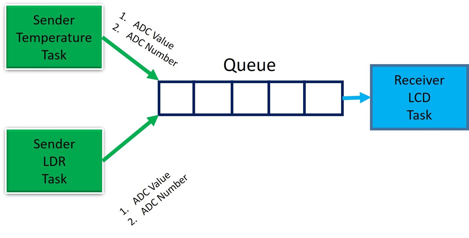
We create an example with Arduino that measure temperature and light sensor value from A0 and A1 channels of Arduino, respectively. After that, prints sensors value on 16×2 LCD.
- First, we create a queue that can hold the structure. This structure elements consist of data value and tag of resource (such as analog channel number)
- In this example, we create two sender tasks such as Temperature and LDR.
- The temperature sender reads the LM35 sensor value from analog channel A0 of Arduino IDE. After that, it writes structure to the queue that contains ADC value and channel number (A0).
- Similarly, a light-dependent resistor task measures light intensity with the ADC channel (A1) and writes data in a structured format.
- LCD task (Receiver) also reads this structure data and processes data to display sensor value after identifying the source.
Implementation of FreeRTOS structure Queue in Arduino
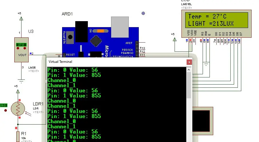
For demonstration, we implement an example using Arduino. Let’s create a demo with two analog sensors and one LCD display as shown in the circuit diagram below:
Circuit Diagram
Connect LM35 and LDR with ADC channels A0 and A1 respectively. Furthermore, also connect 16×2 LCD with Arduino digital pins from D-D7.

You can also reads these posts:
- LCD interfacing with Arduino
- LM35 temperature sensor interfacing with Arduino
- LDR sensor interfacing with Arduino
FreeRTOS Structure Queue Code
First include FreeRTOS, Queue and LCD header files.
// Include Arduino FreeRTOS library
#include <Arduino_FreeRTOS.h>
// include LCD library function
#include<LiquidCrystal.h>
// Include queue support
#include <queue.h>
After that define the pin name that connect with LCD.
//Define LCD pins
LiquidCrystal lcd (7,6,5,4,3,2); //RS, E, D4, D5, D6, D7
We define a structure that consists of two elements such as sensor value and pin number. This structure willbe passed to the queue to write and read sensor output values.
// Define a struct
struct pinRead
{
  int pin;  // analog channel indentifier
  int value; // sensor output value
};
This lines defines the hanlder for structQueue to access it for tasks reference.
QueueHandle_t structQueue;These two functions initialize LCD and Uart communication library.
Serial.begin(9600); // Enable serial communication library.
lcd.begin(16, 2);  // Enable LCD library
Create a structure queue with xQueueCreate() API and pass above defined structure in sizeof() argument.
 // create Structure Queue
structQueue = xQueueCreate(10, // Queue length
             sizeof(struct pinRead) // Queue item size
              );
In the setup function, we create three tasks that use structure_queue to write and read data. Firstly, “TaskLCD” is created that reads structure elements from the queue and it has the highest priority. Conversely, TaskTempReadPin0() and TaskLightReadPin0() pins are created with equal priority and lower than the receiver task. I will explain the reason later on.
if (structQueue != NULL) {

// Create tasks that consume the queue if it was created.
xTaskCreate(TaskLcd, // Task function
            "Displaydata", // A name just for humans
            128,  // This stack size can be checked & adjusted by reading the Stack Highwater
            NULL,
            2, // Priority, with 3 (configMAX_PRIORITIES - 1) being the highest, and 0 being the lowest.
            NULL);


// Create task that publish data in the queue if it was created.
xTaskCreate(TaskTempReadPin0, // Task function
            "AnalogReadPin0", // Task name
            128,  // Stack size
            NULL,
            1, // Priority
            NULL);

// Create other task that publish data in the queue if it was created.
xTaskCreate(TaskLightReadPin1, // Task function
            "AnalogReadPin1", // Task name
            128,  // Stack size
            NULL,
            1, // Priority
            NULL);
}
Receiver Task
“TaskLcd” is a receiver task that reads structure data from struct_queue. The receiving task has the highest priority. Therefore, at the start of program execution, it will run first, but it will enter the blocking state. Because the queue will be empty. Hence, it will execute as soon as when one of the senders will write data to the queue. This task always expects to receive data, therefore, we specify blocking time to the maximum value that is “portMAX_DELAY”.
void TaskLcd(void * pvParameters)
{
(void) pvParameters;
for (;;)
{
int TEMP=0; // temporary variable to hold Temperature adc0 value
int LDR=0; // temporary variable to hold LDR adc1 value
struct pinRead currentPinRead; // structure to hold receiv data
// Read structure elements from queue and check if data received successfully
if (xQueueReceive(structQueue, ¤tPinRead, portMAX_DELAY) == pdPASS)
{
// print received data elements on serial montor
Serial.print("Pin: ");
Serial.print(currentPinRead.pin);
Serial.print(" Value: ");
Serial.println(currentPinRead.value);
// If condition checks, if data receive from channel zero
// If yes, store sensor value member of structure in temporary temp variable
if(currentPinRead.pin==0)
{
TEMP = (currentPinRead.value * 500)/1024; // convert adc value into temperature
// dispay temperature sensor output in first line of 16x2 LCD
lcd.setCursor(0, 0);
lcd.print("Temp = ");
lcd.setCursor(7, 0);
lcd.print(TEMP);
lcd.print("'C");
}
// If condition checks, if data receive from channel one (A1)
// If yes, store sensor value member of structure in temporary LDR variable
if(currentPinRead.pin==1)
{
LDR = map(currentPinRead.value, 0, 1023, 0, 255); //map ADC1 value to light value
// dispay light dependent resistor output in first line of 16x2 LCD
lcd.setCursor(0, 1);
lcd.print("LIGHT = ");
lcd.setCursor(7, 1);
lcd.print(LDR);
lcd.print("LUX");
}
}
taskYIELD(); // terminate the task and inform schulder about it
}
}Sender Tasks
These are the definitions of two sender tasks. As we mentioned earlier, writer tasks have equal priority but lower than receiver tasks. Therefore, when a high priority task will be in the blocking state, then one of the low priority tasks will execute by following time sharing or time-slicing scheduling algorithm. Because FreeRTOS is based on Prioritized Pre-emptive Scheduling with Time Slicing.
// Temperature value and adc number writing
void TaskTempReadPin0(void *pvParameters)
{
(void) pvParameters;
for (;;)
{
struct pinRead currentPinRead; // define a structure of type pinRead
currentPinRead.pin = 0; // assign value '0' to pin element of struct
currentPinRead.value = analogRead(A0); // Read adc value from A0 channel and store it in value element of struct
xQueueSend(structQueue, ¤tPinRead, portMAX_DELAY); //write struct message to queue
Serial.println("Channel_0"); //print Channel_0 on serial monitor
taskYIELD(); //terminate the task and inform schulder about it
}
}
// Light Sensor value and adc number writing
void TaskLightReadPin1(void *pvParameters)
{
(void) pvParameters;
for (;;)
{
struct pinRead currentPinRead; // define a structure of type pinRead
currentPinRead.pin = 1; // assign value '1' to pin element of struct
currentPinRead.value = analogRead(A1); Read adc value from A1 channel and store it in value element of struct
xQueueSend(structQueue, ¤tPinRead, portMAX_DELAY); //write struct message to queue
Serial.println("Channel_1");//print Channel_1 on serial monitor
taskYIELD(); //terminate the task and inform schulder about it
}
}Simulation Result
As you can see the output of this program that displays data received from multiple resources on LCD.
FreeRTOS Structure Queue Arduino Code
This is a complete Code. You can also download complete code from a download link give below.
// Include Arduino FreeRTOS library
#include <Arduino_FreeRTOS.h>
// include LCD library function
#include<LiquidCrystal.h>
//Define LCD pins
LiquidCrystal lcd (7,6,5,4,3,2); //RS, E, D4, D5, D6, D7
// Include queue support
#include <queue.h>
// Define a struct
struct pinRead
{
int pin; // analog channel indentifier
int value; // sensor output value
};
QueueHandle_t structQueue;
void setup()
{
Serial.begin(9600); // Enable serial communication library.
lcd.begin(16, 2); // Enable LCD library
// create Structure Queue
structQueue = xQueueCreate(10, // Queue length
sizeof(struct pinRead) // Queue item size
);
if (structQueue != NULL) {
// Create task that consumes the queue if it was created.
xTaskCreate(TaskLcd, // Task function
"Displaydata", // A name just for humans
128, // This stack size can be checked & adjusted by reading the Stack Highwater
NULL,
2, // Priority, with 3 (configMAX_PRIORITIES - 1) being the highest, and 0 being the lowest.
NULL);
// Create task that publish data in the queue if it was created.
xTaskCreate(TaskTempReadPin0, // Task function
"AnalogReadPin0", // Task name
128, // Stack size
NULL,
1, // Priority
NULL);
// Create other task that publish data in the queue if it was created.
xTaskCreate(TaskLightReadPin1, // Task function
"AnalogReadPin1", // Task name
128, // Stack size
NULL,
1, // Priority
NULL);
}
vTaskStartScheduler();
}
void loop()
{
}
// Temperature value and adc number writing
void TaskTempReadPin0(void *pvParameters)
{
(void) pvParameters;
for (;;)
{
struct pinRead currentPinRead; // define a structure of type pinRead
currentPinRead.pin = 0; // assign value '0' to pin element of struct
currentPinRead.value = analogRead(A0); // Read adc value from A0 channel and store it in value element of struct
xQueueSend(structQueue, ¤tPinRead, portMAX_DELAY); //write struct message to queue
Serial.println("Channel_0"); //print Channel_0 on serial monitor
taskYIELD(); //terminate the task and inform schulder about it
}
}
// Light Sensor value and adc number writing
void TaskLightReadPin1(void *pvParameters)
{
(void) pvParameters;
for (;;)
{
struct pinRead currentPinRead; // define a structure of type pinRead
currentPinRead.pin = 1; // assign value '1' to pin element of struct
currentPinRead.value = analogRead(A1); Read adc value from A1 channel and store it in value element of struct
xQueueSend(structQueue, ¤tPinRead, portMAX_DELAY); //write struct message to queue
Serial.println("Channel_1");//print Channel_1 on serial monitor
taskYIELD(); //terminate the task and inform schulder about it
}
}
void TaskLcd(void * pvParameters)
{
(void) pvParameters;
for (;;)
{
int TEMP=0; // temporary variable to hold Temperature adc0 value
int LDR=0; // temporary variable to hold LDR adc1 value
struct pinRead currentPinRead; // structure to hold receiv data
// Read structure elements from queue and check if data received successfully
if (xQueueReceive(structQueue, ¤tPinRead, portMAX_DELAY) == pdPASS)
{
// print received data elements on serial montor
Serial.print("Pin: ");
Serial.print(currentPinRead.pin);
Serial.print(" Value: ");
Serial.println(currentPinRead.value);
// If condition checks, if data receive from channel zero
// If yes, store sensor value member of structure in temporary temp variable
if(currentPinRead.pin==0)
{
TEMP = (currentPinRead.value * 500)/1024; // convert adc value into temperature
// dispay temperature sensor output in first line of 16x2 LCD
lcd.setCursor(0, 0);
lcd.print("Temp = ");
lcd.setCursor(7, 0);
lcd.print(TEMP);
lcd.print("'C");
}
// If condition checks, if data receive from channel one (A1)
// If yes, store sensor value member of structure in temporary LDR variable
if(currentPinRead.pin==1)
{
LDR = map(currentPinRead.value, 0, 1023, 0, 255); //map ADC1 value to light value
// dispay light dependent resistor output in first line of 16x2 LCD
lcd.setCursor(0, 1);
lcd.print("LIGHT = ");
lcd.setCursor(7, 1);
lcd.print(LDR);
lcd.print("LUX");
}
}
taskYIELD(); // terminate the task and inform schulder about it
}
}Program Time Execution Pattern
Now lets disucss the excution pattern of the program according to tasks priorities:
T1
Receiver Task starts to execute, but enters the blocking state because the queue is empty.
T2
The queue is empty, therefore, one of the low priority tasks starts to execute, because both senders have equal priority. Let’s suppose, AnalogReadPin0 starts to execute and as soon as it writes data to the queue, the high priority task ( receiver) pre-empt it and it will not be able to complete its further execution such as printing “Channel_0” on the serial monitor.
Now the Receiver task being the highest priority one enters the running state and completes its execution such as display temperature on LCD and printing values on the serial monitor. After that, it again goes to a blocking state, because of the queue is empty again.
T3
Now two low priority tasks are available to execute, but this time, the second sender task “AnalogReadPin1” will enter the running state. Because both sender tasks have equal priority and the FreeRTOS scheduler follows a time-sharing algorithm for equal priority tasks. Hence, “AnalogReadPin1” starts to execute.
But as soon as it writes the value of the LDR sensor to the structure queue, “Displaydata” will pre-empt it, because, it is the highest priority task in the blocked state waiting for the data. Therefore, it again enters the running state and completes its execution such as displaying light sensor value on LCD and printing values on the serial monitor. After that, it again goes to a blocking state, because of the queue is empty again.
T4
Now again two sender tasks are ready to execute, but due to time-sharing scheduling for equal priority tasks, “AnalogReadPin0” will start to execute and display “channel_0” on Arduino serial monitor.
T5
After that “AnalogReadPin0” sender task will execute because the receiver task is in a blocking state waiting for the data. Hence, sender2 will display “Channel_2” on the Arduino serial monitor. After that, the program again starts to follow execution from T1.
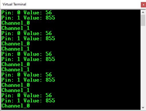
This is the reason we see first LcdTask output on Arduino serial monitor than sender tasks as shown below:
Pin: 0 Value: 56
Pin: 1 Value: 855
Channel_0
Channel_1
Pin: 0 Value: 56
Pin: 1 Value: 855
Channel_0
Channel_1
Pin: 0 Value: 56
Pin: 1 Value: 855
Channel_0
Channel_1
We can also achieve same functionality by using Queue Sets. Read this post on queue sets:
FreeRTOS Queue Sets to Receive Data from Multiple Queues
You may also like to read: