CD4022 is a Johnson Octal johnson Counter IC having eight decoded output pins. These output increments from zero to eight on every positive edge of a clock pulse. It has a feature of antilock gating which assures that counting sequence is correct. This IC is based on TTL logic due to this reason it can also be used with other digital IC’s. It is available in 16-pin PDIP, GDIP, PDSO packages.
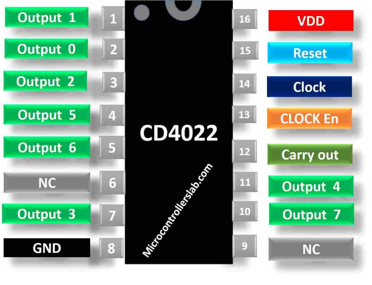
CD4022 Pinout diagram
This divided by 8 counter with 8 decoded outputs has 16 pins. From these 16 pins, eight pins provide 8 decoded sequential outputs. Pinout diagram of CD4022 is shown below:
Pin Configuration Description
It has total of 16 pins. All the pins, their names, and description are mentioned in the table below.
| Pin Number | Pin Name | Description |
|---|---|---|
| 1, 2, 3, 4, 5, 7, 10, 11 | 1, 0, 2, 5, 6, 3, 7, 4 | Output pins |
| 6, 7 | NC | Not Connected |
| 8 | Negative power Supply or ground of the circuit | |
| 12 | CARRY OUT | After counting up to 8, it produces a pulse signal. |
| 13 | CLOCK INHIBIT | When it is LOW or connected with the ground of the circuit, it enables Clock pin. When it is HIGH, the clock pulse is inhibited and so does the counter advancement. |
| 14 | CLOCK | It is a clock signal. When it is High, the counter value is advanced by 1 count. |
| 15 | RESET | It is used to reset the counter value to start counting from beginning or 0. |
| 16 | Positive power supply |
Other Counters ICs
CD4040, CD4060, CD4022, CD4026, CD4020, CD40103, CD4017, 74LS90, 74LS93
CD4022 Electrical Features
- High speed 16 pin CMOS Octal counter which supports 8 decoded outputs
- Schmitt triggered inputs, therefore, unlimited rise and fall time
- Diode protected inputs to protect them against static discharges
- Voltage supply range is from 3V to 15V, typically +5V
- Fully static operation with a clock frequency of 5MHz
- TTL compatible
Equivalent ICs
Where to use CD4022 Sequential Counter?
The IC CD4022 is an octal decoded sequential counter. It turns on 8 decoded outputs in a sequential manner on every positive edge of a clock. It is used in multi-device counting chains to ripple-clock the succeeding device. You can use this IC for counting applications and in devices that are performing arithmetic operations. This IC is best for applications that require sequential counting.
How to use it
This IC is very easy to use. The clock pulse is provided through a 555 timer IC or a switch button. On every positive transition of a clock pulse, the counter value increments by 1 in a sequential manner. The clock inhibits pin inhibits the clock signal. When it is HIGH, the counter value will not increment, and it will inhibit the clock signal. For normal operation, it is connected to the ground. After 10 counts, the carryout pin will go and remain in that condition for 4 counts after that it will go into the LOW state again.
The carry out pin is mostly used in cascading multiple IC’s to increase the counting. It is also used to indicate the status of counting. The reset pin is used to restart the counting from the beginning. If you want to reset the counter value, apply HIGH logic at this pin. This is an example connection diagram.

Now, Connect the eight decoded outputs with LEDs. Connect Vss to the ground and Vdd with the power supply. Switch ON the power supply. The timing diagram given below explains the behavior of eight outputs on applying different combinations of values at inputs.

Proteus Simulation
Example Circuits
This example shows a proteus simulation circuit with a clock source from a 555 timer IC. 555 timer IC provides clock signal to CD4022. You can change the frequency of timer by changing the values of resistors and capacitors. But rest of the working principle is the same as we have seen in the last section.
- As soon as we apply a zero logic to cd4022 counter ic, it starts binary counting sequentially. LEDs display the output.
- Counting stops when we apply logic high to clock disable pin. But counter starts counting from the same position when we again apply logic zero this E pin.

Applications
This IC has numerous applications in electronic circuits. Some of them are given below:
- Binary counter or Binary decoder for counting
- frequency division
- Octal Counters or Octal counter display
- Instrumentation and Remote metering
- LED chasers, LED matrix, LED drivers and other digital arithmetic applications and projects
- Timers
- Can be used for divide by 8 counting
- Automotive, medical electronic and Alarm systems
- Arithmetic Logic Units of computers for performing calculations
2D Diagram

DataSheet
Other Electronics Components:
- TDA7294 DMOS Audio Amplifier
- In-Depth Guide: NE556 Dual Timer IC
- LM1117 800-mA Low-Dropout Linear Regulator
- MCP3008 8-Channel 10-Bit A/D Converters with SPI Serial Interface
- AD623 Low-Cost Instrumentation Amplifier
- LM386 Low Voltage Audio Power Amplifier
- CA3130 MOSFET Input BiMOS OP-AMP IC
- RB156 Bridge Rectifier 1.5 Ampere
- 28BYJ-48 5 volt Stepper Motor Guide
- TP4056 Linear Lithium-Ion Battery Charging Module
- UCC25600 High-Performance Resonant Mode Controller
- LM723 Variable Voltage Regulator
- In Depth Guide: LM317 3-Terminal Adjustable voltage Regulator