CD4026 is a 5 stage johnson decade counter belonging to a CD4000 series. It has many distintive features than other decade counters. Firstly, it is ideal for applications having low power consumption requirement. Secondly, CD4026 counts from 0 to 9 and then resets to 0. Additionally, the advantage of using this IC is that it has a built-in decoder circuit along with the counter and it can be connected to all types of 7-segment displays.The ten decoding outputs go high sequentially on positive edge of input clock cycle.
Recommended Components
The following parts are used in this article, along with a generic electronics kit that is handy for building and testing the circuit.
| Component | How it’s used | Buy on Amazon |
|---|---|---|
| CD4026 decade counter | The CD4026 decade counter with 7-segment outputs this article covers. | Check Price |
| Electronic component assortment kit (1390 pcs) | A handy assortment of resistors, capacitors, LEDs, diodes and transistors for building circuits. | Check Price |
| Digital multimeter (AstroAI) | Measures voltage, current, resistance and checks continuity while you build and debug. | Check Price |
| Breadboard | Solderless base for prototyping the circuit. | Check Price |
| Jumper Wires | Make the connections on the breadboard. | Check Price |
As an Amazon Associate we earn from qualifying purchases. Prices and availability are accurate as of the date/time indicated and are subject to change.
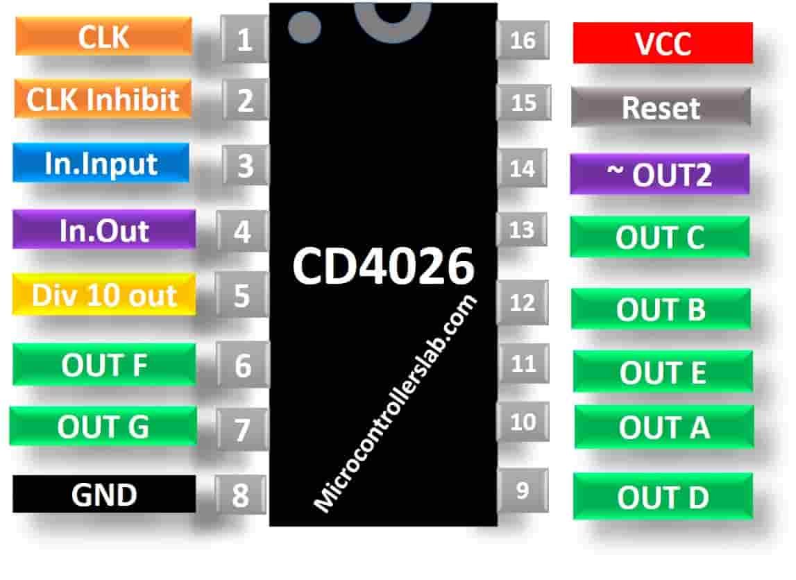
CD4026 Pinout Diagram
This picture shows a pinout diagram of 5-stage johnson decade counter. It is a 16 pin IC available in different packages.
Pin Configuration Details
This table lists the pin description of johson counter along with the funtionality.
| Pin Name | Description |
|---|---|
| CLOCK | Clock pulse is responsible for the counting. When it is HIGH, counter starts counting. CLOCK signal is applied through 555 timer or other IC’s. |
| CLK Inhibit | Clock inhibit input enables clock pin. When it is LOW or connected with the ground of the circuit, it enables Clock pin. When it is HIGH, the clock pulse is inhibited. |
| Enable Input | When it is HIGH, it enables the output pins.When it is LOW, the outputs are forced to be LOW regardless of the state of counter. |
| Enable Output | This pin is always High and is used for cascading multiple IC’s. |
| Divide by10 Output | It is a Carry-Out Output pin. After counting up to 9, it produces a pulse signal. It is used in cascading to clock the succeeding decade. |
| A, B, C, D, E, F, G Output | These seven pins are decoded outputs which are connected to the seven-segment display to represent the decimal digits. |
| Gnd | This pin is connected to the ground of circuit |
| Not 2 Out | Ungated C segment output pin is only used for some dividing functions. It is HIGH by default and will set to LOW when the counter reaches 2. |
| Reset | When reset pin is HIGH, it clears the counter value to zero. |
| Vcc | Voltage supply is connected to this pin. |
CD4026 Counter Features
- It acts as a counter for seven-segment display
- If you want to display numbers greater than 9, this can be achieved by cascading multiple IC’s.
- Can drive a common cathode 7-Segment display directly
- The clock input is Schmitt triggered to provide a reliable clock signal and therefore it has no fall and rises time limitations.
- It is TTL compatible and can be easily interfaced with timer or microcontrollers
- The maximum clock frequency is 6Mhz.
- In summary, it is available in four types of 16-pin packages which include PDIP, GDIP, PDSO.
Other Counters ICs: CD4020, CD4022, CD4060, CD40102, CD4017, CD4026, 74LS93
Proteus Simulation
Where to use it?
This CD4026 IC performs digital displays as it can convert input into a decimal digit which can be seen on the Common Cathode Type 7-segment display. Furthermore, It has both a counter and a decoder. Due to this feature, it doesn’t require a separate decoder IC for driving a 7-segment display. Although, we can use along with microcontrollers for displaying analogue values but it will be a wastage of resources. This IC can count from 0 to 9 but you can increase the counting by giving high clock pulse. For displaying bigger numbers, multiple IC’s can be cascaded.

Therefore, it can be used in all those applications and projects whose operation involves counting events or objects based on some condition.
How to use CD4026 Counter?
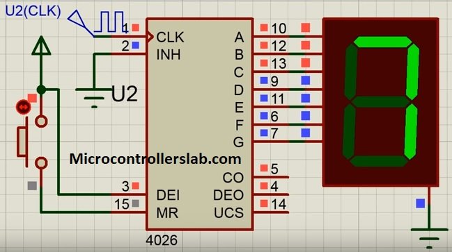
In normal operation, the IC is supplied with +5V at Vcc and Gnd pin is connected to the ground of the circuit but it can work in a voltage range of 3V to 18V. The seven decoded outputs are connected directly to the inputs of the Common Cathode Type of 7-segment display.
The clock signal is provided using 555 timer IC or any TTL compatible IC which generate pulses of high and low voltages. After that pressing the switch, counter starts and gets incremented by 1 after every positive edge of clock. For example, you are using a clock of frequency 10Hz.
T=1/f=1/10=0.1s
Therefore, after every 0.1s counter gets incremented by 1. The clock inhibit pin is connected to ground to send the clock signals to IC. First time number 1 will be displayed on the 7-segment display. On pressing the switch second time, number 2 will be displayed and the process continues till counting reaches to 9. After that, it will restart from 0.
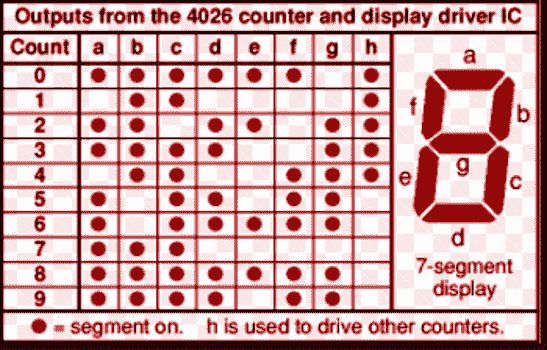
Ouput Pattern Table
The table given below shows the sequence of outputs from the CD4026 counter IC after pressing switch connected to the clock pin and how it is displayed on the 7-segment display.
For displaying bigger numbers, multiple IC’s are cascaded using Carry over pin and Enable Output pin. Enable output pin is set to HIGH. It drives the cascaded IC clock pin when its own counter reaches the value of 9. However, If you want to restart the counter from 0, press the reset pin.
CD4026 Example Circuits
In this section, we will see some basic and popular example circuits of this johnson counter. Firstly, we will see an single digital circuit that can count from 0-9. After that we will discuss a 2 digit display circuit that can count from 00-99. But you can also extend this circuit to count upto 000-999. At the end, we will see a practical example such as digital clock design.
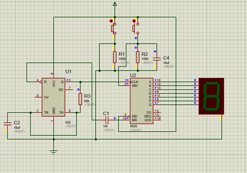
Single Digit Counter Example
This circuit can count from 0-9. Because we use only one CD4026 IC and one seven segment display. The speed of counting display depends on the clock frequency. Pin3 should remain active high. We can use pin15 to stop counter from working. You can change the frequency according to your requirement.
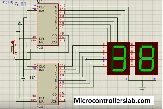
2 Digit Counter Example
Similarly, if you want to design a two digital counter circuit, you will need to two CD4026 decoders and two 7-segment displays. This works similar to the last circuit. But the only difference is the use of CO pin and clock pin use for second display. Because we want to increment 10th place 7-segment value only after unit place 7-segment complete its counting from 0-9 and resets. After every reset, CO pin sends active high signal to second IC.
In short, This signal acts like a positive edge clock. Therefore, counter increments its value on every reset of first johnson counter integrated circuit. Additionally, you can add one more digit to this circuit.
Digital Clock using CD4026
In conclusion, we will provide you an practical example. This is circuit diagram of digital clock using CD4026. Therefore, if you do not want to use microcontroller. You can still design a digital clock using this digital decoder. Check this complete video guide for step by step guide.
Applications
- Digital Clocks, Timer circuits and frequency dividers
- Registers to process data
- Counter projects to count events, objects or people
- Multiple ICs can display larger numbers between 0-999
- Eliminate the need of microcontroller for counter design
Alternative options
In summary, you can also see these alternative options available.
Other Electronics Components
- TEENSY 3.6 development board
- LT3750 Capacitor Charge Controller IC
- TLE4999I3 Hall Effect Sensors
- BMP280 Barometric Pressure and Temperature Sensor Module
- MQ137 Ammonia Gas Sensor Interfacing with Arduino
- TMP36 Low Voltage Temperature Sensor
- TDA2005 20W bridge/stereo amplifier for car radio
- LM1084 5-A Low Dropout Positive Regulator
- HX711 24-Bit Analog-to-Digital Converter (ADC) for Weigh Scales
- TDA1554 single-ended or BTL Audio Amplifier
- UM3561 Three Siren Sound Generator IC
please put the circuit diagram of 4026 and 7411 digital clock on your site.