In this tutorial, we will learn to interface a flex sensor with Arduino. In the starting sections, we will see bend sensor introduction, pinout, working principle, and how to use it with our Arduino board. Secondly, we will see an example to show resistance and bent angle readings obtained from the sensor on the Serial Monitor. In the second example, we will display flex sensor readings on 16×2 LCD.
Introduction to Flex Sensor
A Flex sensor measures the amount of bending or deflection. It consists of a carbon surface on a plastic strip. When the strip is bent or deflected then the resistance of this flex sensor is changed therefore it is also called a bend sensor. Because its changing resistance is directly proportional to the amount of bend, therefore, it is also known as a ‘flexible potentiometer’ that can also be used as a goniometer.
There are two types of flex sensors currently used in the industry according to their size. They come in two different sizes: 2.2 inches and 4.5 inches. The resistance and size of both are different but the working principle is the same. So the appropriate size is chosen according to the requirement.

In this guide, we will use the 2.2-inch flex sensor. These types of flex sensors have been using in different applications such as in security systems, rehabilitation, computer interface, music interface, servo motor control, intensity control, or where the user wants to change the resistance during bending. These are easily available in the market or online shops.
Specifications
The table below shows some key specifications of the flex sensor.
| Specification | Value |
|---|---|
| Operating Voltage | 0-5V |
| Power Rating | 0.5W continuous |
| Operating Temperature | from -45ºC to +80ºC |
| Flat Resistance (Nominal) | 25kΩ |
| Resistance Tolerance | ±30% |
| Resistance Range | from 45k to 125kΩ |
Flex Sensor Working
This sensor device works on the principle of bending the strip away from the ink. When the strip is bent then its resistance is changed which is measured with any controller. In other words, this sensor works like a variable resistance whose resistance is changed when it is bent. This change in resistance depends upon surface linearity, which means the resistance of this sensor would be different at different angles. This can be seen in the figure below:
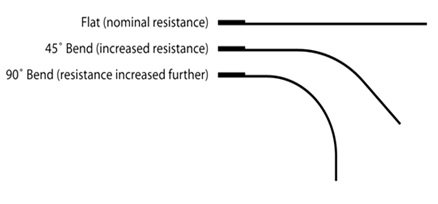
When the sensor is flat (no bending) the resistance is lowest and at a nominal value. The resistance increases linearly as the bending angle increases. When the bend in a flex sensor is 45 degrees then the resistance would be double as compared to when it was flat. Similarly, when the bend in the sensor is 90 degrees then the resistance would be double as compared to 45 degrees and four times as compared to when it is flat. So, if we talk about ratio then this resistance is directly proportional to bending angle means it increases linearly.
Obtaining Variable Voltage Output from the bending effect of sensor
In order to obtain a reading from the flex sensor, we will connect it with a fixed resistor. As the flex sensor itself acts as a variable resistor due to its bending effect thus, it will follow a voltage divider configuration.
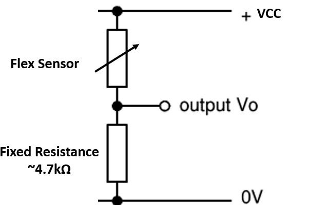
Our voltage divider configuration consists of the variable resistor that is the flex sensor and a fixed resistor of 4.7k ohms. To obtain Vo, the output voltage across the fixed resistor, the following voltage divider formula will be used:
Vo=(4.7k/4.7k+R flex)*VCC
You know that as the bending angle of the flex sensor increases, R flex increases linearly. Thus following the voltage divider equation for Vo, the increase in R flex will result in a direct decrease in Vo whenever the flex sensor will be bent further. This will cause the Vo to vary linearly with increasing resistance. We will use this varying voltage output to obtain a digital value by connecting it to an ADC pin of the Arduino board.
Pin Configuration of Flex Sensor
A Flex sensor consists of two pins: p1 and p2. It does not have any polarized terminal like a capacitor or diode, which means there is no positive or negative terminal. For powering on this flex sensor 3.3V to 5V dc voltage are applied on its terminals and these voltages are gained from an interfacing device which could be any type of controller. These voltages are applied according to the below table.
| P1 | It is the first one pin and is usually connected to the positive terminal of the power source. |
| P2 | It is the second pin and is usually connected to the ground pin of the power source. |
Interfacing Flex Sensor with Arduino
In this section, we will show you how to connect the flex sensor with Arduino to be able to get the readings from the sensor.
Required Components:
- Arduino board
- Flex Sensor
- 4.7k ohm resistor
- Breadboard
- Connecting Wires
Follow the schematic diagram below to connect the two devices together. We are using the 4.7k ohm as a pull-down resistor and connecting it in series with the sensor, in this case, to form a voltage divider configuration as seen above. The ADC pin A2 is connected in between the flex sensor pin 2 and 4.7k ohm resistor.

Arduino Sketch: Displaying Voltage in Serial Monitor
Open your Arduino IDE and go to File > New to open a new file. Copy the code given below in that file and save it.
This sketch will be able to display the resistance values in the serial monitor according to the bending angle of the flex sensor.
const int ADC_pin = A2;
const float VCC = 5;
const float fixed_resistor = 4700.0;

void setup() {
  Serial.begin(9600);
  pinMode(ADC_pin, INPUT);
}

void loop() {
  int flex_ADC = analogRead(ADC_pin);
  float flex_voltage = flex_ADC * VCC / 1023.0;
  float flex_resistance = (fixed_resistor * (VCC / flex_voltage - 1.0))/1000;
  Serial.print("ADC value: ");
  Serial.println(flex_ADC);
  Serial.print("Volatge value: " );
  Serial.println(flex_voltage);
  Serial.println("Resistance value: " + String(flex_resistance) + " kilo-ohm");

  Serial.println();
  delay(500);
}
How the Code Works?
We will first define some variables which we will use later on in the program sketch. This includes the integer variable ADC_pin that saves the Arduino ADC pin connected with the flex sensor. It is A2 in our case. Moreover, we also include two floating variables. One is VCC and the other is the fixed resistor that we are using to build the voltage divider circuit. It is 4700 ohm i.e. 4.7k ohm in our case.
const int ADC_pin = A2;
const float VCC = 5;
const float fixed_resistor = 4700.0;
Inside the setup() function we will open the serial communication at a baud rate of 9600 and then set the ADC pin as an input pin.
void setup() {
  Serial.begin(9600);
  pinMode(ADC_pin, INPUT);
}
Inside the infinite loop() function, we will first find out the ADC value according to the bending angle using analogRead(). We will pass the ADC pin connected to the sensor as an argument inside it. This will be stored in the integer variable flex_ADC.
int flex_ADC = analogRead(ADC_pin)Then, we will convert this ADC value to a voltage by using the following formula.
float flex_voltage = flex_ADC * VCC / 1023.0;In order to find the resistance, we will use the voltage divider formula and divide it by 1000 to get the resistance in kilo-ohms.
float flex_resistance = (fixed_resistor * (VCC / flex_voltage - 1.0))/1000;Now, we will print all these three values in the serial monitor with a delay of 0.5 seconds.
  Serial.print("ADC value: ");
  Serial.println(flex_ADC);
  Serial.print("Volatge value: " );
  Serial.println(flex_voltage);
  Serial.println("Resistance value: " + String(flex_resistance) + " kilo-   ohm");
  Serial.println();
  delay(500);
Demonstration
Choose the correct board and COM port before uploading your code to the board.
Go to Tools > Board and select Arduino UNO

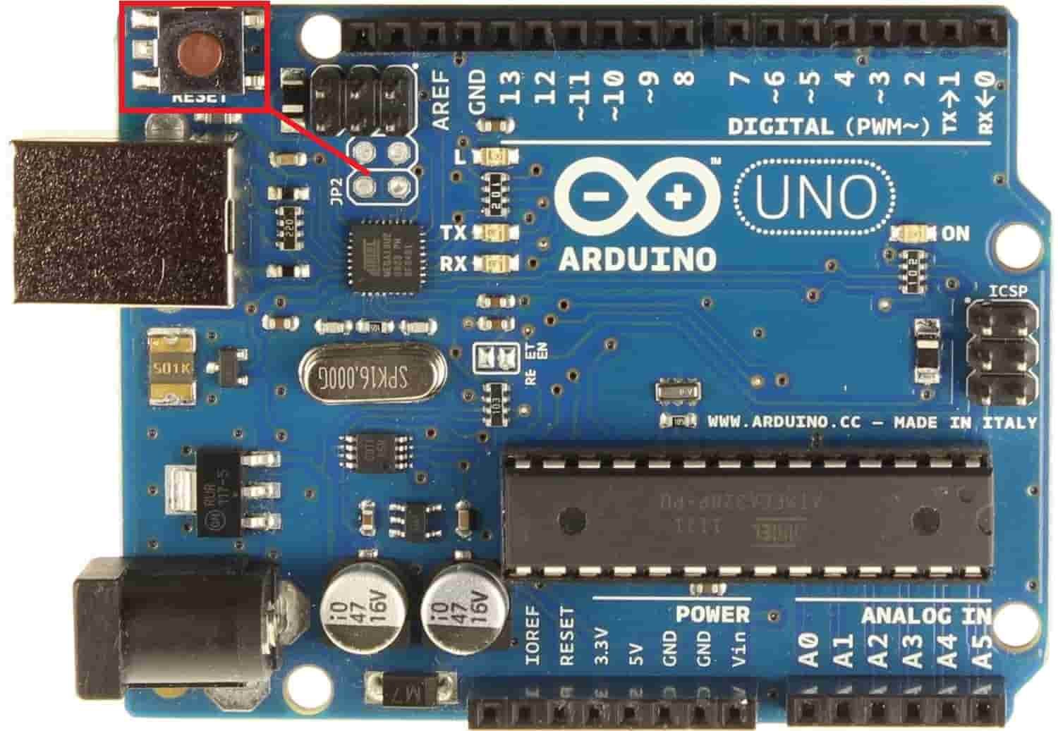
Next, go to Tools > Port and select the appropriate port through which your board is connected. Click on the upload button to upload the code into the Arduino development board. After you have uploaded your code to the Arduino press its RST button.
In your Arduino IDE, open up the serial monitor and you will be able to see the various readings as you bend the flex sensor.

Displaying Flex Sensor Readings on 16×2 LCD
In this section, we will display the same flex sensor readings which we previously printed on the serial monitor but now on a 16×2 LCD display. We have a dedicated tutorial regarding interfacing 16×2 LCD display with Arduino with some example sketches. Have a look at it before proceeding further for a better understanding of the LCD.
Recommended Reading: 16×2 LCD Interfacing with Arduino – Explained with Example Codes
16×2 LCD introduction and Pin out
There are two types of pins on the whole 16×2 LCD module. Some pins are used to send to 16×2 LCD and some are command pins. In other words, every pin has a role in controlling a single pixel on the display.16 x 2 LCD has sixteen columns and two rows. That means, it can display sixteen characters per row and it has two such rows.
Pin out
The diagram shows the pin configuration of a 16×2 LCD display. It has sixteen pins.

- D0 – D7: Pin number 7-14 are data bus lines that are used to send data from Arduino which you want to display on LCD. With these 8 data lines, data can be transferred either in an 8-bit format or in a 4-bit format. In a 4-bit format, only upper four bits (D4-D7) are used to send data from Arduino to LCD. The full byte is transmitted in two successive transmissions. A 4-bit format is used to save GPIO pins of Arduino. Because fewer GPIO pins of Arduino will be required to transfer data.
- Contrast Select (VEE): It will help to control the contrast of PIXELS according to the 16X2 LCD light.
- RS: This pin is known as a register select pin. It helps to toggle the command/data register.
- R/W: The signal on this pin will decide whether it is going to read from LCD or write on it.
- EN: Enable pin will help to transfer the instruction from the data pins and another command pin to the LCD. It act as permission to internal registers.
- VSS: It’s a ground pin for common grounds.
- VCC: The power pin will use for voltage input to the 16X2 LCD.
In Arduino, we don’t need to worry about controlling these data lines and control registers. Because Arduino provides rich library resources. LCD library comes with Arduino IDE by default when we install it.
16×2 LCD Module interfacing with Arduino and Flex Sensor
Now we will learn how to connect a 16×2 LCD module with Arduino and flex sensor to display readings.
Required Components:
- Arduino
- Flex Sensor
- 16×2 LCD
- 4.5k ohm resistor
- 220 ohm resistor
- Connecting wires
- Breadboard
Follow the table below to make the connection diagram accordingly.
Connections between 16×2 LCD and Arduino:
| 16×2 LCD | Arduino |
|---|---|
| D4-D7 | 5, 4, 3, 2 |
| E | 11 |
| RS | 12 |
| VEE | GND |
| VCC | 5V |
| LED+ | 5V |
| LED- | GND with 220-ohm resistor |
| VSS | GND |
The connections between the Flex sensor and Arduino UNO are the same as we did previously.
Follow the schematic diagram below to connect all three devices properly. We are following the same connections as specified in the table.
Schematic Diagram

Arduino Sketch: Displaying Resistance from Flex Sensor on 16×2 LCD
Open your Arduino IDE and go to File > New to open a new file. Copy the code given below in that file and save it.
This sketch will be able to display the resistance values on the 16×2 LCD according to the bending angle of the flex sensor.
#include<LiquidCrystal.h>
const int ADC_pin = A2;
const float VCC = 5;
const float fixed_resistor = 4700.0;
int flex_ADC;
LiquidCrystal lcd(12, 11, 5, 4, 3, 2);

void setup()
{
 lcd.begin(16, 2);
}

void loop()
{
  flex_ADC = analogRead(ADC_pin);
  Serial.println(flex_ADC);
  float flex_volatge = flex_ADC * VCC / 1023.0;
  float flex_resistance = (fixed_resistor * (VCC / flex_volatge - 1.0))/1000;
  lcd.setCursor(0,0);
  lcd.print("Resistance: ");
  lcd.setCursor(0,1);
  lcd.print(flex_resistance);
  lcd.setCursor(8,1);
  lcd.print("kohm");
  }
Most of the code is the same as the one in the previous sketch. We have incorporated a 16×2 LCD now. We will display the resistance in kilo-ohms on the LCD.
Firstly, we will include the library necessary for the functionality of the LCD. This library contains prototypes and function definitions that are used to control display.
#include<LiquidCrystal.h>The second most important thing is the declaration of Arduino pins that are connected with the LCD. To define connections, we use the following line of code. This line creates a LiquidCrystal object and lcd is a name of the object that we are going to use to call LCD functions. You can also use any other name.
LiquidCrystal lcd(rs, en, d4, d5, d6, d7)In our case, the pins are 12, 11, 5, 4, 3, and 2 respectively.
LiquidCrystal lcd(12, 11, 5, 4, 3, 2);Till now, we have defined the LCD connection and included its library. After that, we must define the size of the LCD. Inside the setup() function we will call lcd.begin(). This routine is used to define the size of an LCD. The first argument to this function is a number of rows and the second argument is a number of columns. For instance, this line declares the size as 16 columns and 2 rows. That means 16×2 size.
void setup()
{
 lcd.begin(16, 2);
}
Inside the loop() function we will obtain the reading for the resistance according to the bending angle of the flex sensor and display it on the LCD.
  float flex_resistance = (fixed_resistor * (VCC / flex_volatge - 1.0))/1000;
  lcd.setCursor(0,0);
  lcd.print("Resistance: ");
  lcd.setCursor(0,1);
  lcd.print(flex_resistance);
  lcd.setCursor(8,1);
  lcd.print("kohm");
Demonstration
Choose the correct board and COM port before uploading your code to the board.
Go to Tools > Board and select Arduino UNO
Next, go to Tools > Port and select the appropriate port through which your board is connected. Click on the upload button to upload the code into the Arduino development board. After you have uploaded your code to the Arduino press its RST button.
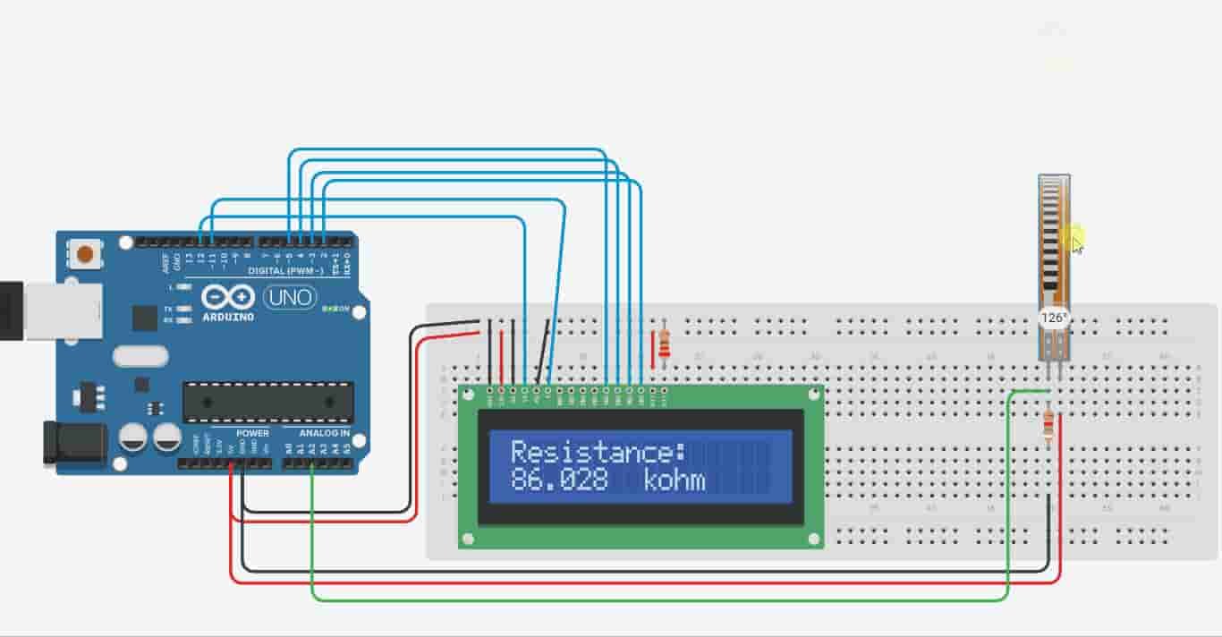
In your Arduino IDE, open up the serial monitor and you will be able to see the various readings. Likewise, the 16×2 LCD will start displaying the resistance as you bend the flex sensor.
Simulation
Conclusion
In conclusion, we looked upon the flex sensor and its programming with the Arduino development board. We have learned how to obtain bent angle and resistance value from the flex sensor and used two sketches to program an Arduino board.