What is Force Sensing Resistor? Normally, in this world materials are easily available whose resistance is changed by mechanically stress ,pressure or force. Similarly, if we talk about this FSR 400 force sensing resistor then this sensing resistor is also made with that material whose resistance is changed, when mechanically force or pressure is applied on this material. Actually, this sensing resistor has made with conductive polymer material which has a property of increasing resistance when force or pressure is applied on its conductive surface. This force sensing resistor has thin size, low cost and good shock resistance. It has so many applications such as in automobile industry like car sensors, resistive touch pads, musical instruments, key pads, portable electronics system and foot pronation system etc. These sensors are easily available in market or online shop. A simple force sensing resistor is shown in figure 1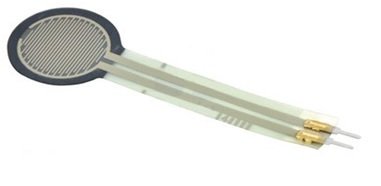
Figure 1 A Simple FSR 400 Force Sensing Resistor
Pin Configuration of FSR 400 Force Sensing Resistor
Every force sensing resistor consists of two pins. First one is directly connected to source and second one is connected to ground through a pull down resistor. There is point between pull down resistor and force sensing resistor shown in figure 2, this point is directly connected to analogue input of any controller which is used with this sensing resistor for measuring purposes.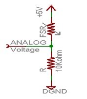
Figure 2 Force Sensing Resistor with Pull Down Resistor
According to figure 2 force sensing resistor is powered up with 3.3V to 5V dc voltages. But when we connect this force sensing in this configuration shown in figure 2 then the total resistance of pull down resistor and force sensing resistor is decreased from 10K ohm to 10K ohm. This means when resistance is decreased then current flowing through force sensing resistor is increased. Similarly, the voltages across 10 K ohm resistor is also increased. There is an equation which is used for output voltages is this Vo = Vcc ( R / (R + FSR) ). But this equation is only valid for linear resistivity for not linear voltages. In this equation output voltages are inversely proportional to force sensing resistance.
Working Principle of FSR 400 Force Sensing Resistor
Force sensing resistor works on two principles first one is percolation in which conductive polymer material particles move and filter and second one is quantum tunneling in which conductive polymer material particles passes through potential barrier that is not so much difficult. Actually, both principles are occurred simultaneously during working condition of this force sensing resistor, but one dominates the other one this depends upon the polymer material particles concentration and particle concentration is referred to as volume fraction.
This was the inside material process which have done in force sensing resistor during its working condition but if we talk in electronic language. Then this is connected with any controller such as microcontroller or Arduino etc. After connecting when any mechanical force, pressure or stress is applied on this force sensing resistor then its resistance is decreased. Means, its resistance is inversely proportional to applied force, pressure or stress. This decreased in resistance is measured by microcontroller or Arduino etc. So, this was simple working principle of this force sensing resistor.
How to Interface FSR 400 Force Sensing Resistor with Arduino Board: Currently, force sensing resistor have been using in different applications, but it could not be used lonely, a controller is must required to use it in any application. Here we shell tell the user how interface the FSR 400 force sensing resistor with Arduino board. For interfacing it with Arduino board connection are made according to figure 3 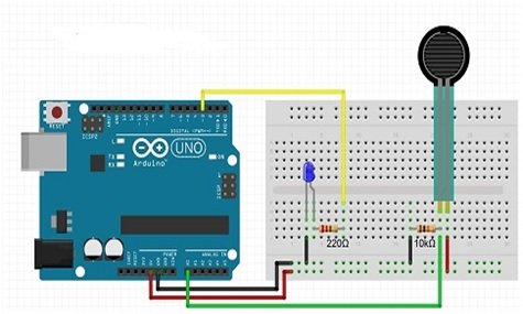
Figure 3 Interfacing of FSR 400 Force Sensing Resistor with Arduino Board
For making connection, a LED is connected at output side of Arduino board for checking the resistance, means how it increase or decrease. For checking this, a logic program is written in Arduino library and then it is up load in Arduino board with the help of Arduino IDE software . When program is up load then turn on the Arduino board when it is turned on the it power on the LED. Similarly, when we apply some force or pressure on sensing resistor then its light is change due its resistance change.