HMC5883L is a magnetometer module developed by Honeywell using anisotropic magnetoresistive technology. It is a multichip module that behaves as a digital compass IC to find the direction and measures the magnitude and direction of the magnetic field along the X, Y and Z-axis. HMC5883L module converts the magnetic field into differential voltage output on 3 axis pins.
Why we Need Magnetometer?
The unmanned machines like robots and drones cannot sense in which direction to move, unlike humans. Therefore, they need a sensor to identify directions. Therefore, we need magnetometers. They sense the magnetic field and based on this magnetic field; it tells the direction of a device in which this magnetometer is integrated. Hence, we can use HMC5883L to determine the direction of objects
HMC5883L IC Pinout Diagram
HMC5883L magnetometer module consists of XC6206P332MR IC along with other components. Now let’s first discuss the pin configuration of this IC and after that we will see pinout of the module.


IC Pin Configuration
This section provides the details of all pins of the HMC5883L IC. Pin 3, 5, 6, 7 and 14 are NC pins. They do not have any function and that’s why left unconnected.
I2C Communication Pins
Pin1 and pin16 are communication pins for the I2C interface.
- SCL – Pin1
- SDA – Pin16
SCL is a master/slave clock input which receives clock signal from a master device. Magnetometer IC acts as a slave when we interface it with microcontroller. Hence, microcontroller provides clock signal to IC. SDA is a serial data pin.
Power Supply Pins
Pin2 is a power supply pin. It requires voltage in a range of 2.16V to 3.6V for the sensor to operate. It provides power for internal operations. Pin9 and Pin11 are ground pins.
- Pin_4 is the S1 pin. Tie this pin to VDDIO.
- Pin_8 is a set/reset strap positive input pin. It removes the past magnetism stored in the sensor.
- Pin_10 is a pin for a reservoir capacitor. Connect a 4.7 µF reservoir capacitor at this pin.
- Pin_12 SETC is a connection on the driver side of set/reset strap.
- Pin_13 VDDIO supplies power to the IO interface. It should be 1.71V to VDD.
- Pin_15 is a data Ready interrupt pin which indicates when data is ready.
HMC5883L Module Pinout
As you can see that XC6206P332MR IC has a lot of pins and we need to use external components to make it work. But fortunately, module is available in market with all required components. This figure shows the pinout of the magnetometer module.
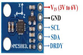
As you can see from this pinout diagram that this module is easy to use and has fewer pins. The function of all pins are the same. SCL and SDA pins are used to interface with microcontrollers to receive 3-axis data from the magnetometer.
Features
- It operates with a DC Voltage ranging from 3V to 6V.
- It supports
communication protocol.
- The sensor has 3-Axis Magnetoresistive Sensors, ASIC, 12-bit ADC and strap drive circuits.
- The HMC2883L measures strength of magnetic field in a range of -8 to +8 gauss with an accuracy of 1-2 degree.
- The maximum data output rate is 160Hz.
Where to use it?
HMC5883L is a small sensor which is cheap and easily available. Its digital digital interface allows it to use with other microcontrollers. You can even connect it with normal IC’s. These are the most reliable and sensitive sensors as compared to other magnetometers in the industry.
You can use this sensor in applications to measure the strength and magnitude of magnetic field. It can also measure the magnetization of a material also. If you are looking for a magnetometer that can perform above functions by giving precise measurements, then this sensor would serve best for this purpose.
How to use HMC5883L?
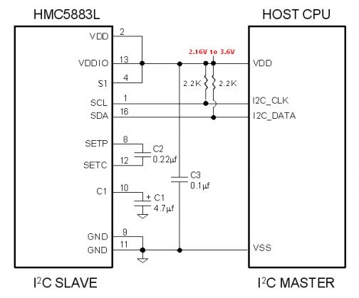
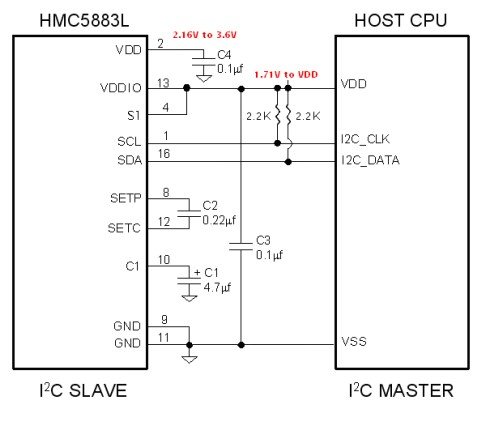
Figures below show two reference designs of the HMC5883L sensor module to understand its working. In single supply design, apply same voltage supply at both pins VDD and VDDIO. While in dual supply mode, we have applied separate power supplies at both pins. VDD provides power to internal operations of IC whereas VDDIO supplies power to interface to enable communication. All other connections in both circuits are same. It has two modes of operation standard and fast mode. Therefore, we connect pull up resistors to support these modes.
Single Supply Design
Dual Supply design
Interfacing of HMC5883L with Arduino Uno
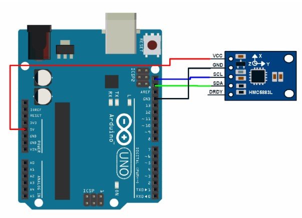
The HMC5883L has a breakout board which consists of extra circuitry to make it compatible for use with other microcontrollers. You can directly connect this breakout board with Arduino Uno without the need of extra components. The connections are simple. Connect Vcc to +5V and ground to the ground pin of Arduino. Connect the communication pins SCL and SDA to analog pin 5 and 4 or Arduino.
HMC5883 Arduino Library
Programming of this HMC5883 module is very easy with James Sleeman’s HMC5883L library. First of all, go to this link and download the library.
After that go to Arduino library manager and add the HMC5883 library. Or you can extract the downloaded folder and paste this file inside the Arduino libraries folder.
Connection Diagram with Arduino
Make connection with magnetometer module and Arduino Uno according to this schematic diagram.
- GY-273 Compass Module -> Arduino
- VCC -> VCC (See Note Below)
- GND -> GND
- SCL -> A5/SCL, (Use Pin 21 on the Arduino Mega)
- SDA -> A4/SDA, (Use Pin 20 on the Arduino Mega)
- DRDY -> Not Connected (in this example)
Arduino Code
This code shows the functions of HMC5883L module Arduino Library.
#include <Arduino.h>

// PLEASE NOTE!
// The Arduino IDE is a bit braindead, even though we include Wire.h here, it does nothing
// you must include Wire.h in your main sketch, the Arduino IDE will not include Wire
// in the build process otherwise.
#include <Wire.h>
#include "HMC5883L_Simple.h"

HMC5883L_Simple::HMC5883L_Simple()
{
  declination_offset_radians = 0;
  mode = COMPASS_SINGLE | COMPASS_SCALE_130 | COMPASS_HORIZONTAL_X_NORTH;
  i2c_address = COMPASS_I2C_ADDRESS;  // NB: The HMC5883L does not appear to be able to have any different address.
                                      //     so this is a bit moot.
}

/** Set declination in degrees, minutes and direction (E/W)
 *   See http://www.magnetic-declination.com/
 */

void HMC5883L_Simple::SetDeclination( int declination_degs , int declination_mins, char declination_dir )
{
  // Convert declination to decimal degrees
  switch(declination_dir)
  {
    // North and East are positive
    case 'E':
      declination_offset_radians = ( declination_degs + (1/60 * declination_mins)) * (M_PI / 180);
      break;

    // South and West are negative
    case 'W':
      declination_offset_radians =  0 - (( declination_degs + (1/60 * declination_mins) ) * (M_PI / 180));
      break;
  }
}

/** Set the sampling mode to one of COMPASS_CONTINUOUS or COMPASS_SINGLE
 */

void HMC5883L_Simple::SetSamplingMode( uint16_t sampling_mode )
{
  // Mode is the bits marked M in mode
  //    xxxxxxxxxxxSSSMM
  mode = (mode & ~0x03) | (sampling_mode & 0x03);

  Write(COMPASS_MODE_REGISTER, mode & 0x03);
}

/** Set the scale to one of COMPASS_SCALE_088 through COMPASS_SCALE_810
 * Higher scales are less sensitive and less noisy
 * Lower scales are more sensitive and more noisy
 */

void HMC5883L_Simple::SetScale( uint16_t scale )
{
  // Scale is the bits marked S in mode
  //    xxxxxxxxxxxSSSMM
  mode = (mode & ~0x1C) | (scale & 0x1C);

  Write(COMPASS_CONFIG_REGISTER_B, (( mode >> 2 ) & 0x07) << 5);
}

/** Set the orientation to one of COMPASS_HORIZONTAL_X_NORTH
 * through COMPASS_VERTICAL_Y_WEST
 *
 */

void HMC5883L_Simple::SetOrientation( uint16_t orientation )
{
  // Orientation is the bits marked XXXYYYZZZ in mode
  //    xxXXXYYYZZZxxxxx
  mode = (mode & ~0x3FE0) | (orientation & 0x3FE0);
}

/** Get the heading of the compass in degrees. */
float HMC5883L_Simple::GetHeadingDegrees()
{
  // Obtain a sample of the magnetic axes
  MagnetometerSample sample = ReadAxes();

  float heading;

  // Determine which of the Axes to use for North and West (when compass is "pointing" north)
  float mag_north, mag_west;

  // Z = bits 0-2
  switch((mode >> 5) & 0x07 )
  {
    case COMPASS_NORTH: mag_north = sample.Z; break;
    case COMPASS_SOUTH: mag_north = 0-sample.Z; break;
    case COMPASS_WEST:  mag_west  = sample.Z; break;
    case COMPASS_EAST:  mag_west  = 0-sample.Z; break;

    // Don't care
    case COMPASS_UP:
    case COMPASS_DOWN:
     break;
  }

  // Y = bits 3 - 5
  switch(((mode >> 5) >> 3) & 0x07 )
  {
    case COMPASS_NORTH: mag_north = sample.Y;  break;
    case COMPASS_SOUTH: mag_north = 0-sample.Y; ;  break;
    case COMPASS_WEST:  mag_west  = sample.Y;  break;
    case COMPASS_EAST:  mag_west  = 0-sample.Y;  break;

    // Don't care
    case COMPASS_UP:
    case COMPASS_DOWN:
     break;
  }

  // X = bits 6 - 8
  switch(((mode >> 5) >> 6) & 0x07 )
  {
    case COMPASS_NORTH: mag_north = sample.X; break;
    case COMPASS_SOUTH: mag_north = 0-sample.X; break;
    case COMPASS_WEST:  mag_west  = sample.X; break;
    case COMPASS_EAST:  mag_west  = 0-sample.X; break;

    // Don't care
    case COMPASS_UP:
    case COMPASS_DOWN:
     break;
  }

  // calculate heading from the north and west magnetic axes
  heading = atan2(mag_west, mag_north);

  // Adjust the heading by the declination
  heading += declination_offset_radians;

  // Correct for when signs are reversed.
  if(heading < 0)
    heading += 2*M_PI;

  // Check for wrap due to addition of declination.
  if(heading > 2*M_PI)
    heading -= 2*M_PI;

  // Convert radians to degrees for readability.
  return heading * 180/M_PI;
}


/** Read the axes from the magnetometer.
 * In SINGLE mode we take a sample.  In CONTINUOUS mode we
 * just grab the most recent result in the registers.
 */

HMC5883L_Simple::MagnetometerSample HMC5883L_Simple::ReadAxes()
{
  if(mode & COMPASS_SINGLE)
  {
    Write(COMPASS_MODE_REGISTER, (uint8_t)( mode & 0x03 ));
    delay(66); // We could listen to the data ready pin instead of waiting.
  }

  uint8_t buffer[6];
  Read(COMPASS_DATA_REGISTER, buffer, 6);

  MagnetometerSample sample;

  // NOTE:
  // The registers are in the order X Z Y  (page 11 of datasheet)
  // the datasheet when it describes the registers details then in order X Y Z (page 15)
  // stupid datasheet writers
  sample.X = (buffer[0] << 8) | buffer[1];
  sample.Z = (buffer[2] << 8) | buffer[3];
  sample.Y = (buffer[4] << 8) | buffer[5];

  return sample;
}

/** Write data to the compass by I2C */
void HMC5883L_Simple::Write(uint8_t register_address, uint8_t data)
{
  Wire.beginTransmission(i2c_address);
  Wire.write(register_address);
  Wire.write(data);
  Wire.endTransmission();
}

/** Read data from the compass by I2C
 */
uint8_t HMC5883L_Simple::Read(uint8_t register_address, uint8_t buffer[], uint8_t length)
{
  // Write the register address that we will begin the read from, this
  // has the effect of "seeking" to that register
  Wire.beginTransmission(i2c_address);
  Wire.write(register_address);
  Wire.endTransmission();

  // Read the data starting at that register we seeked
  Wire.requestFrom(i2c_address, length);

  if(Wire.available() == length)
  {
    for(uint8_t i = 0; i < length; i++)
    {
      buffer[i] = Wire.read();
    }

    return length;
  }

  return 0;
}
Example Code
This example sketch shows a reading of a heading from an HMC5883L triple-axis magnetometer on the Arduino Serial monitor.
#include <Arduino.h>
#include <Wire.h>
#include <HMC5883L_Simple.h>

// Create a compass
HMC5883L_Simple Compass;

void setup()
{
  Serial.begin(9600);
  Wire.begin();

  // Magnetic Declination is the correction applied according to your present location
  // in order to get True North from Magnetic North, it varies from place to place.
  //
  // The declination for your area can be obtained from http://www.magnetic-declination.com/
  // Take the "Magnetic Declination" line that it gives you in the information,
  //
  // Examples:
  //   Christchurch, 23° 35' EAST
  //   Wellington  , 22° 14' EAST
  //   Dunedin     , 25° 8'  EAST
  //   Auckland    , 19° 30' EAST
  //
  Compass.SetDeclination(23, 35, 'E');

  // The device can operate in SINGLE (default) or CONTINUOUS mode
  //   SINGLE simply means that it takes a reading when you request one
  //   CONTINUOUS means that it is always taking readings
  // for most purposes, SINGLE is what you want.
  Compass.SetSamplingMode(COMPASS_SINGLE);

  // The scale can be adjusted to one of several levels, you can probably leave it at the default.
  // Essentially this controls how sensitive the device is.
  //   Options are 088, 130 (default), 190, 250, 400, 470, 560, 810
  // Specify the option as COMPASS_SCALE_xxx
  // Lower values are more sensitive, higher values are less sensitive.
  // The default is probably just fine, it works for me.  If it seems very noisy
  // (jumping around), incrase the scale to a higher one.
  Compass.SetScale(COMPASS_SCALE_130);

  // The compass has 3 axes, but two of them must be close to parallel to the earth's surface to read it,
  // (we do not compensate for tilt, that's a complicated thing) - just like a real compass has a floating
  // needle you can imagine the digital compass does too.
  //
  // To allow you to mount the compass in different ways you can specify the orientation:
  //   COMPASS_HORIZONTAL_X_NORTH (default), the compass is oriented horizontally, top-side up. when pointing North the X silkscreen arrow will point North
  //   COMPASS_HORIZONTAL_Y_NORTH, top-side up, Y is the needle,when pointing North the Y silkscreen arrow will point North
  //   COMPASS_VERTICAL_X_EAST,    vertically mounted (tall) looking at the top side, when facing North the X silkscreen arrow will point East
  //   COMPASS_VERTICAL_Y_WEST,    vertically mounted (wide) looking at the top side, when facing North the Y silkscreen arrow will point West
  Compass.SetOrientation(COMPASS_HORIZONTAL_X_NORTH);

}

// Our main program loop.
void loop()
{
   float heading = Compass.GetHeadingDegrees();

   Serial.print("Heading: \t");
   Serial.println( heading );
   delay(1000);
}
Applications
- GPS based wireless phones
- computer games
- wireless pointers
- sport watches
- portable GPS receivers
Using the provided code I am receiving the same heading over and over while moving the board in different directions.
Compile has no errors.
The displayed heading is 339.08 and never changes.
Any ideas?
Pat Kirk