RB156 Bridge Rectifier is a full bridge rectifier transistor IC. It offers 1.5 Ampere output load current and 50-900 Volts. Furthermore, it consumes very low reverse biasing current and low forward drop voltages. Most importantly, it has a very high dielectric strength.
Bridge Rectifier Introduction
The process of converting a bidirectional current (AC) into a unidirectional current (DC) is known as rectification. Rectification can be performed by using two methods which are:
- Half-wave rectification: It takes only half part of the AC wave either positive or negative as an input while blocking other parts.
- Full-wave rectification: It uses both positive and negative cycles of alternating current and converts them into a smooth DC current.
The Bridge rectifiers are used to perform the process of rectification. RB156 is one of these bridge rectifiers. It performs rectification with the help of a full-bridge rectifier circuit integrated inside the chip.
RB156 Bridge Rectifier Pinout Diagram
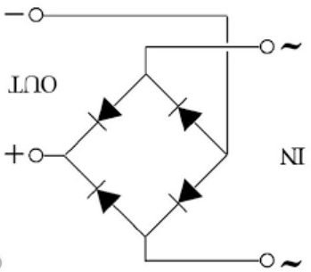
It is a four-terminal device and internally consists of four diodes.
Pin Configuration Description
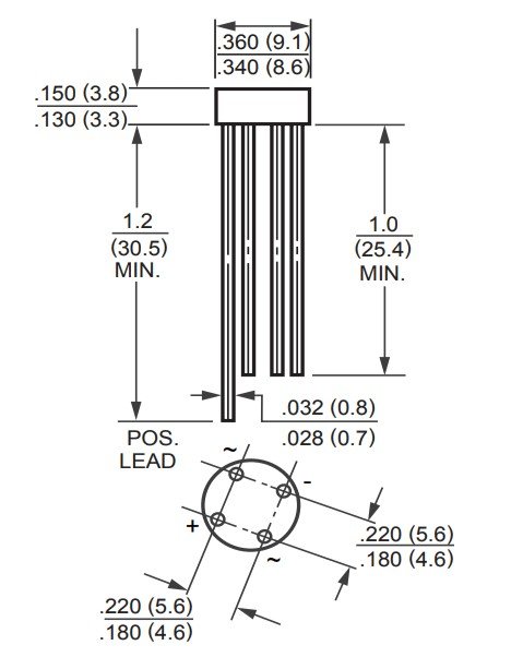
RB156 Bridge Rectifier consists of four pins in which two pins are AC input pins and the other two are DC output pins.
Pin# 01: Phase (AC)
It is an input pin where the phase wire of AC voltage supply is connected.
Pin# 02: Neutral (AC)
It is an input pin where the neutral wire of the AC voltage supply is connected.
Pin# 03: Positive (DC)
It is the output pin from where the rectified DC signal is obtained.
Pin# 04: Negative (DC)
It is the output pin that sends out a ground voltage signal of a rectifier.
RB156 Bridge Rectifier Features
The features and technical specifications of RB156 Bridge rectifier are given below:
- It is a low cost, single-phase rectifier which can operate in a range of -55 °C to +125 °
- The Maximum Input Voltage (VRMS) of this bridge rectifier is 560V and the maximum Peak Reverse Voltage is 800V.
- It has a high reverse voltage of up to 1000V.
- The output voltage is 2 volts and the voltage drop per bridge is 1V.
- The maximum value of DC current at the output is 1.5A and that of surge current is 50A.
Where to use it?
This IC is used mainly in power appliances for converting Alternating current to Direct current. It is also used in single-phase mains supply due to its capability large input voltage. You can use this IC application requiring AC to DC conversion and need the above-mentioned features.
How to use RB156 Bridge Rectifier?
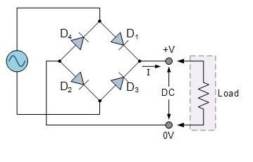
The rectifying circuit inside this IC is a single phase. Single-phase bridge rectifiers use four diodes for rectifying the input. The main advantage of using bridge rectifiers instead of a full-wave rectifier is that the output voltage of the bridge rectifier is double than the output voltage of full-wave rectifiers. All these diodes are connected in a configuration shown below.
Full Bridge Rectifier Working Principle
All these four diodes are connected in series with each other. During each half-cycle, only two diodes will conduct. During the positive half cycle of the alternating voltage supply, diodes D1 and D2 will become forward biased whereas the diodes D3 and D4 are reverse biased. Therefore, only D1 and D2 will conduct. The circuit diagram is shown below.
On the other hand, during the negative half cycle of the alternating voltage supply, diodes D1 and D2 will be reverse biased and are turned off. This time only diodes D3 and D4 will conduct in series. In both positive and negative half-cycles, the current flowing through the load connected at the output will have the same direction. As the current direction is the same, the DC current is obtained. A capacitor is connected in parallel to increase the average DC level at the output. It acts as a smoothing capacitor which converts the rippled DC output into a smooth DC signal.
RB156 Bridge Rectifier Applications
The few applications of the RB156 Bridge rectifier are mentioned below:
- Performing operation of rectification in electric circuits
- Conversion of AC to DC signals
- Battery chargers
- Power supplies


