In this user guide, we will discuss how to configure STM32 Nucleo timer module in counter mode. To use the timer as a counter, we will configure it in input-edge counter mode. In input edge capture counter mode, timers of stm32 start to count whenever an external event occurs on the input edge capture GPIO pin. We will program STM32 Nucleo in STM32CubeIDE using HAL libraries.
As discussed earlier, we will be using STM32CubeIDE, therefore, you should have the latest version installed on your system. You can follow this guide to install it:
STM32 Nucleo Timer Counter Mode
The Nucleo STM32F103RB comes with four timers known as TIM1, TIM2, TIM3, and TIM4. They act as a clock and are used to keep track of time based events. The timer module can work in different configurations such as timer mode, counter mode, PWM mode, output compare mode, etc. This guide focuses on configuring the timer module in counter mode.
When configuring the STM32 Nucleo timer module in counter mode, an external source such as the timer input pin clocks the timer module. The timer can count up/down on every rising/falling edge of the timer input pin. The counter mode is useful when creating a digital counter that does not require polling input pins or reading a GPIO pin periodically or regularly triggering interrupts. Another thing of importance while working in counter mode is that it allows the user to monitor the frequency of the counter through the number of pulses that occurred at each interval through the counter difference.
Modes for Counting
When setting the timer module operation in counter mode, there are three different counting modes the user can choose from. This includes the up-counting, down-counting, and center-aligned modes.
| Up-Counting Mode | In this mode the counter starts from 0 to the auto-reload value that is set by the user. When the counter counts till the auto-reload value, the counter overflows and it is restarted again from 0. When the counter overflows, an update event can also be set. |
| Down-Counting Mode | In this mode the counter starts from the auto-load value and counts down to 0. When the counter reaches 0, the counter underflow occurs and the counter restarts again from the auto-reload value. When the counter underflows, an update event can also be set. |
| Center Aligned Mode | This counting mode is also known as Up/Down mode. In this mode the counter starts from 0 to the auto-reload value. When the auto-reload value is reached, the counter overflow occurs. The counter then restarts from the auto-reload value to 1 and then the counter underflow occurs. This causes the counter to restart from 0. |
Setup STM32 Nucleo Timer as a Digital Counter in CubeIDE
Let’s create and build a project in STM32 CubeIDE to create a simple digital counter by configuring the timer in counting mode where the mode of counting will be set as up-counting mode.
Open the CubeIDE and head over to a new project.
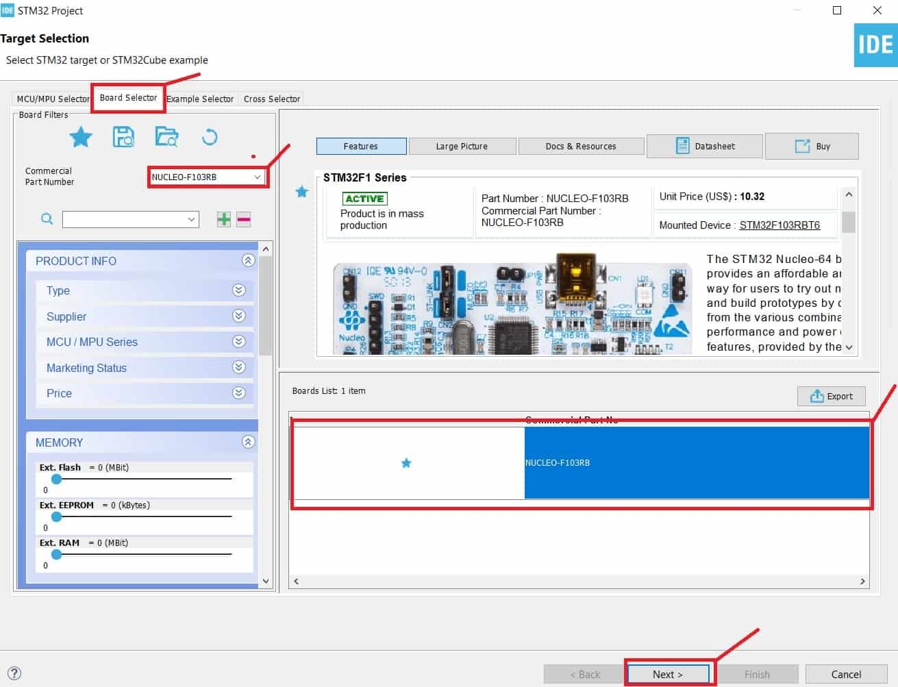
Then for the target selection, specify the STM32 Nucleo board number. After that click on any column as shown in the picture below. Then click the ‘Next’ button.
Specify the name of your project then click ‘Finish’ to complete the setup of your project.
Clock Configuration
Go to System Core > RCC then select ‘Crystal/Ceramic Resonator’ in from the High Speed Clock feature.

Now we have enabled the RCC external clock source.
Next go to the Clock Configuration found at the top. This will open the following window. Here we will select the clock frequency.
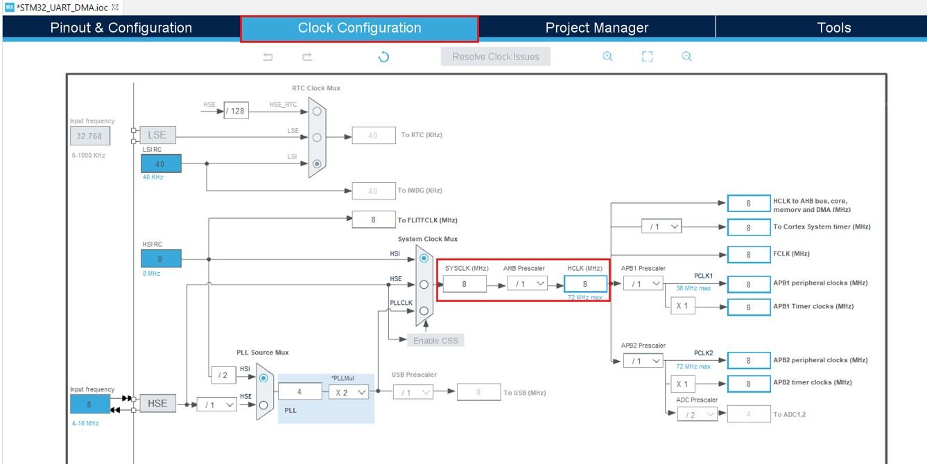
You can specify your system clock. We will set it as 72 MHz. These are the configurations we have set:

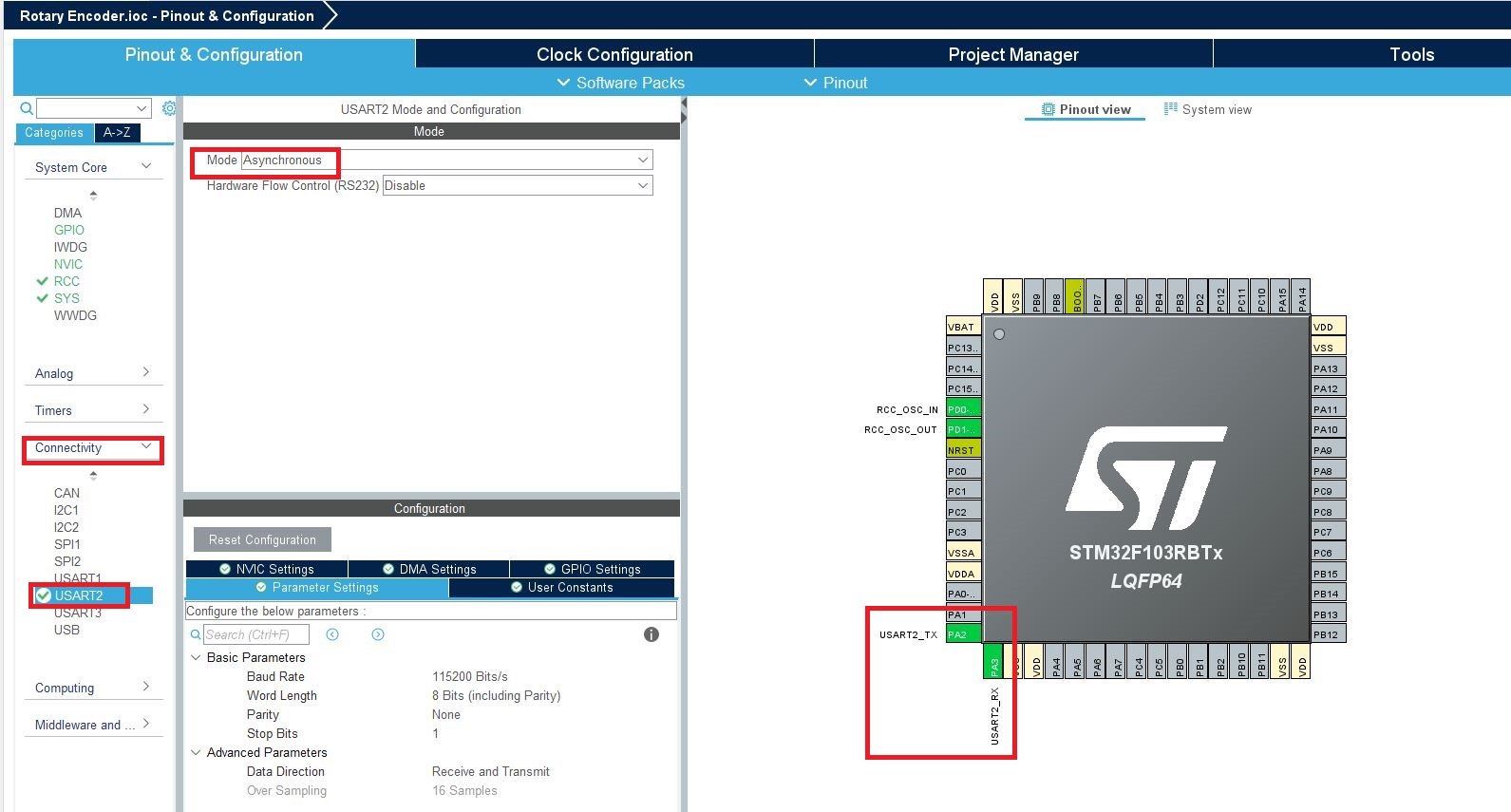
Now head over to Connectivity > USART2 and set the mode as ‘Asynchronous.’ You can also view the parameter settings of the UART including the baud rate, word length, parity, etc.
Setup Timer in Counter Mode
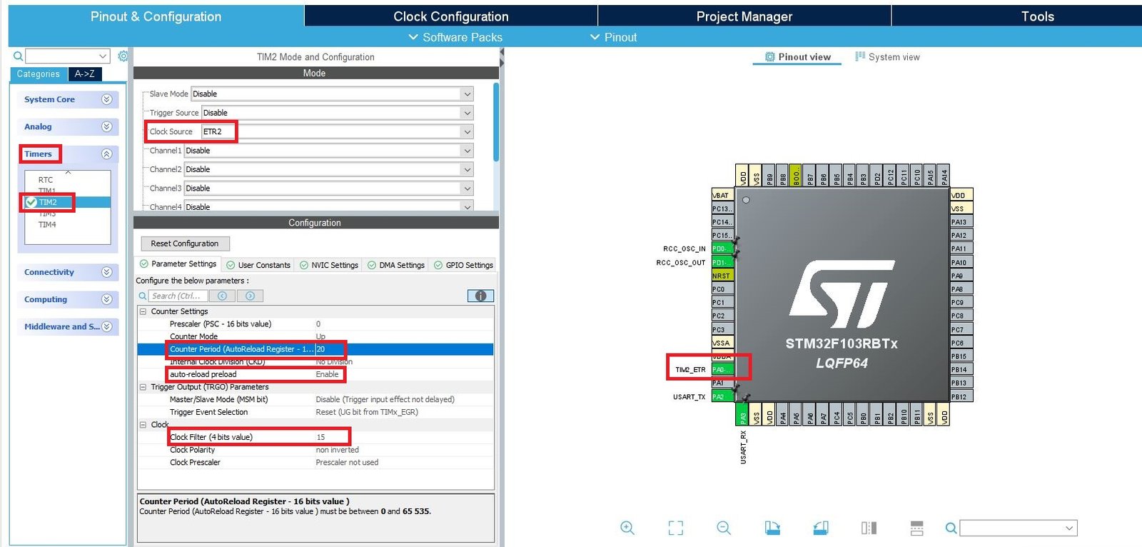
Now head over to Timers to configure the timer to work in counter mode. We have selected Timer2. For the clock source, we have specified it as ‘ETR2’ which means an external pin which is set as PA0. This pin will be connected with a push button that will be used to clock the timer module.
Now go to the Parameter Settings and set the counter settings. As you may note the counter mode is set up as ‘Up.’ The counter period or the auto-reload value is set as 20. This means when the counter will count till 20, the counter overflow will occur thus triggering an interrupt. Also remember to enable the auto-reload preload. Moreover, we have set the clock filter value as 15. This will help to reduce the noise on the input pin that could occur due to the push button bouncing effect. Also, the rising edge of the input pin PA0 is set for the counter to count.
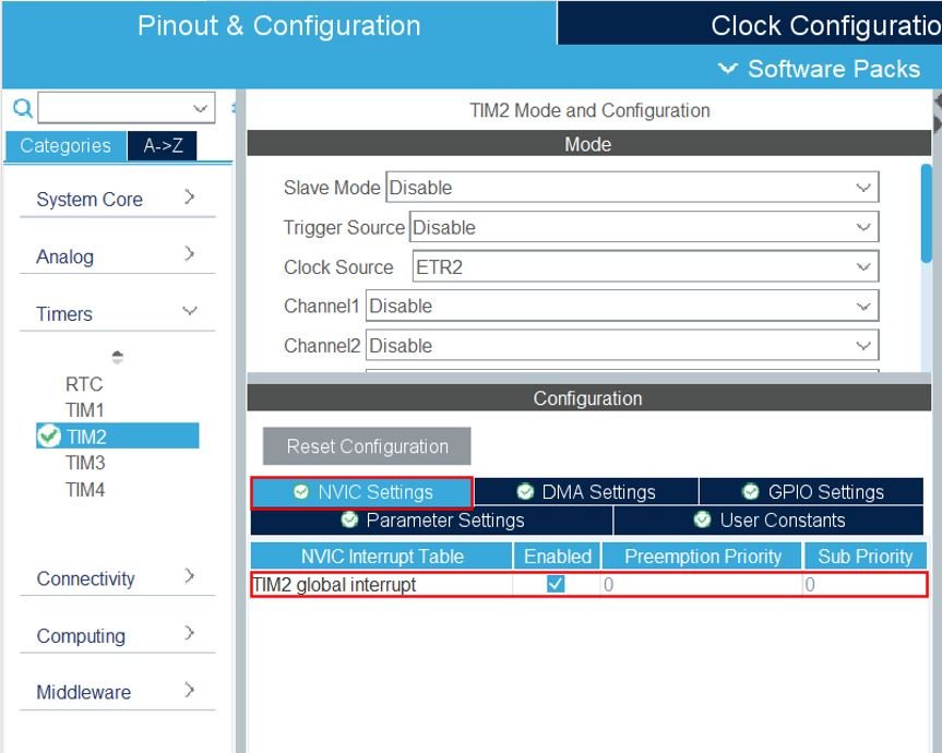
To enable the TIM2 global interrupt, head over to NVIC Settings inside Timers > TIM2 and enable it.
Now we will save our file. Press Ctrl + S. The following window will appear. Click ‘Yes.’ This will generate a template code for you.

Another window will appear that will ask if you want to open the perspective. Click ‘Yes.’

Digital Counter with STM32 Nucleo Code
We will set up a code in which the Timer2 counter counts the ticks from 0 to 20, when the tick count reaches 20, a timer interrupt is triggered which denotes that an overflow occurred and the counter restarts again. We will monitor the counter values in the serial terminal by connecting our STM32 Nucleo using UART2 pins that we set up. The data will be printed through UART2 in the form of a string.
Now let us look at our main.c file that was generated.
Look for the MX_TIM2_Init() function.
static void MX_TIM2_Init(void)
{

  /* USER CODE BEGIN TIM2_Init 0 */

  /* USER CODE END TIM2_Init 0 */

  TIM_ClockConfigTypeDef sClockSourceConfig = {0};
  TIM_MasterConfigTypeDef sMasterConfig = {0};

  /* USER CODE BEGIN TIM2_Init 1 */

  /* USER CODE END TIM2_Init 1 */
  htim2.Instance = TIM2;
  htim2.Init.Prescaler = 0;
  htim2.Init.CounterMode = TIM_COUNTERMODE_UP;
  htim2.Init.Period = 20;
  htim2.Init.ClockDivision = TIM_CLOCKDIVISION_DIV1;
  htim2.Init.AutoReloadPreload = TIM_AUTORELOAD_PRELOAD_ENABLE;
  if (HAL_TIM_Base_Init(&htim2) != HAL_OK)
  {
    Error_Handler();
  }
  sClockSourceConfig.ClockSource = TIM_CLOCKSOURCE_ETRMODE2;
  sClockSourceConfig.ClockPolarity = TIM_CLOCKPOLARITY_NONINVERTED;
  sClockSourceConfig.ClockPrescaler = TIM_CLOCKPRESCALER_DIV1;
  sClockSourceConfig.ClockFilter = 15;
  if (HAL_TIM_ConfigClockSource(&htim2, &sClockSourceConfig) != HAL_OK)
  {
    Error_Handler();
  }
  sMasterConfig.MasterOutputTrigger = TIM_TRGO_RESET;
  sMasterConfig.MasterSlaveMode = TIM_MASTERSLAVEMODE_DISABLE;
  if (HAL_TIMEx_MasterConfigSynchronization(&htim2, &sMasterConfig) != HAL_OK)
  {
    Error_Handler();
  }
  /* USER CODE BEGIN TIM2_Init 2 */

  /* USER CODE END TIM2_Init 2 */

}
This is the initialization function for Timer2. It configures the Timer2 on the set Prescaler, Preload and Clock frequency values.
Modifying Code
Inside the main.c file, make sure the following code is part of your script by including the lines of code given below.
#include "main.h"
#include "stdio.h"
TIM_HandleTypeDef htim2;

UART_HandleTypeDef huart2;

uint8_t end_message[40] = "Overflow Reached! Counter is Reset\n\r";

void SystemClock_Config(void);
static void MX_GPIO_Init(void);
static void MX_TIM2_Init(void);
static void MX_USART2_UART_Init(void);

int main(void)
{

	uint8_t message[20] = {'\0'};
	uint16_t tick_count = 0;

   /* Reset of all peripherals, Initializes the Flash interface and the Systick. */
  HAL_Init();

  /* Configure the system clock */
  SystemClock_Config();

  /* Initialize all configured peripherals */
  MX_GPIO_Init();
  MX_TIM2_Init();
  MX_USART2_UART_Init();

  HAL_TIM_Base_Start_IT(&htim2);

  while (1)
  {
      tick_count = TIM2->CNT;
      sprintf(message, "Tick Count = %d\n\r", tick_count);
      HAL_UART_Transmit(&huart2, message, sizeof(message), 100);
      HAL_Delay(100);
  }

}

void HAL_TIM_PeriodElapsedCallback(TIM_HandleTypeDef* htim)
{
    HAL_UART_Transmit(&huart2, end_message, sizeof(end_message), 100);
}
We will first enable the timer in the following lines. Firstly, call MX_TIM2_Init() function to initialize Timer2 on the set Prescaler, Preload and Clock frequency values. Then call HAL_TIM_Base_Start_IT() to start the TIM Base generation in interrupt mode. It takes in a single parameter which is the pointer to the TIM_HandleTypeDef structure that holds the configuration parameters for the timer module. It is ‘&htim2’ in our case.
TIM_HandleTypeDef htim2;
MX_TIM2_Init();
HAL_TIM_Base_Start_IT(&htim2);
Inside the while() loop, the ticks count is read and transmitted via UART2 to the serial terminal after a delay of one second.
 while (1)
  {
      tick_count = TIM2->CNT;
      sprintf(message, "Tick Count = %d\n\r", tick_count);
      HAL_UART_Transmit(&huart2, message, sizeof(message), 100);
      HAL_Delay(100);
  }
Then we will add the timer interrupt ISR handler callback function. This callback function is called whenever the timer overflows. It is responsible to transmit the end_message through UART2 when the counter overflows using HAL_UART_Transmit(). The end_message is defined at the start of the code which holds the message “Overflow Reached! Counter is Reset.”
void HAL_TIM_PeriodElapsedCallback(TIM_HandleTypeDef* htim)
{
    HAL_UART_Transmit(&huart2, end_message, sizeof(end_message), 100);
}
You can view the the timer interrupt handler in the stm32f1xx_it.c file.
void TIM2_IRQHandler(void)
{
  HAL_TIM_IRQHandler(&htim2);
}
The timer interrupt ISR handler callback function name is provided in the timer interrupt handler routine.
void HAL_TIM_IRQHandler(TIM_HandleTypeDef *htim)
{
  /* TIM Update event */
  if (__HAL_TIM_GET_FLAG(htim, TIM_FLAG_UPDATE) != RESET)
  {
    if (__HAL_TIM_GET_IT_SOURCE(htim, TIM_IT_UPDATE) != RESET)
    {
      __HAL_TIM_CLEAR_IT(htim, TIM_IT_UPDATE);
      #if (USE_HAL_TIM_REGISTER_CALLBACKS == 1)
        htim->PeriodElapsedCallback(htim);
      #else
        HAL_TIM_PeriodElapsedCallback(htim);
      #endif /* USE_HAL_TIM_REGISTER_CALLBACKS */
    }
  }
}
main.c file
This is how a complete main.c file will be after modification.
/* USER CODE BEGIN Header */
/**
  ******************************************************************************
  * @file           : main.c
  * @brief          : Main program body
  ******************************************************************************
  * @attention
  *
  * Copyright (c) 2024 STMicroelectronics.
  * All rights reserved.
  *
  * This software is licensed under terms that can be found in the LICENSE file
  * in the root directory of this software component.
  * If no LICENSE file comes with this software, it is provided AS-IS.
  *
  ******************************************************************************
  */
/* USER CODE END Header */
/* Includes ------------------------------------------------------------------*/
#include "main.h"

/* Private includes ----------------------------------------------------------*/
/* USER CODE BEGIN Includes */
#include "stdio.h"
/* USER CODE END Includes */

/* Private typedef -----------------------------------------------------------*/
/* USER CODE BEGIN PTD */

/* USER CODE END PTD */

/* Private define ------------------------------------------------------------*/
/* USER CODE BEGIN PD */

/* USER CODE END PD */

/* Private macro -------------------------------------------------------------*/
/* USER CODE BEGIN PM */

/* USER CODE END PM */

/* Private variables ---------------------------------------------------------*/
TIM_HandleTypeDef htim2;

UART_HandleTypeDef huart2;

/* USER CODE BEGIN PV */
uint8_t end_message[40] = "Overflow Reached! Counter is Reset\n\r";
/* USER CODE END PV */

/* Private function prototypes -----------------------------------------------*/
void SystemClock_Config(void);
static void MX_GPIO_Init(void);
static void MX_USART2_UART_Init(void);
static void MX_TIM2_Init(void);
/* USER CODE BEGIN PFP */

/* USER CODE END PFP */

/* Private user code ---------------------------------------------------------*/
/* USER CODE BEGIN 0 */

/* USER CODE END 0 */

/**
  * @brief  The application entry point.
  * @retval int
  */
int main(void)
{
  /* USER CODE BEGIN 1 */
	uint8_t message[20] = {'\0'};
	uint16_t tick_count = 0;

  /* USER CODE END 1 */

  /* MCU Configuration--------------------------------------------------------*/

  /* Reset of all peripherals, Initializes the Flash interface and the Systick. */
  HAL_Init();

  /* USER CODE BEGIN Init */

  /* USER CODE END Init */

  /* Configure the system clock */
  SystemClock_Config();

  /* USER CODE BEGIN SysInit */

  /* USER CODE END SysInit */

  /* Initialize all configured peripherals */
  MX_GPIO_Init();
  MX_USART2_UART_Init();
  MX_TIM2_Init();
  /* USER CODE BEGIN 2 */
  HAL_TIM_Base_Start_IT(&htim2);
  /* USER CODE END 2 */

  /* Infinite loop */
  /* USER CODE BEGIN WHILE */
  while (1)
  {
	  	tick_count = TIM2->CNT;
		sprintf(message, "Tick Count = %d\n\r", tick_count);
		HAL_UART_Transmit(&huart2, message, sizeof(message), 100);
		HAL_Delay(100);
    /* USER CODE END WHILE */

    /* USER CODE BEGIN 3 */
  }
  /* USER CODE END 3 */
}

/**
  * @brief System Clock Configuration
  * @retval None
  */
void SystemClock_Config(void)
{
  RCC_OscInitTypeDef RCC_OscInitStruct = {0};
  RCC_ClkInitTypeDef RCC_ClkInitStruct = {0};

  /** Initializes the RCC Oscillators according to the specified parameters
  * in the RCC_OscInitTypeDef structure.
  */
  RCC_OscInitStruct.OscillatorType = RCC_OSCILLATORTYPE_HSE;
  RCC_OscInitStruct.HSEState = RCC_HSE_BYPASS;
  RCC_OscInitStruct.HSEPredivValue = RCC_HSE_PREDIV_DIV1;
  RCC_OscInitStruct.HSIState = RCC_HSI_ON;
  RCC_OscInitStruct.PLL.PLLState = RCC_PLL_ON;
  RCC_OscInitStruct.PLL.PLLSource = RCC_PLLSOURCE_HSE;
  RCC_OscInitStruct.PLL.PLLMUL = RCC_PLL_MUL9;
  if (HAL_RCC_OscConfig(&RCC_OscInitStruct) != HAL_OK)
  {
    Error_Handler();
  }

  /** Initializes the CPU, AHB and APB buses clocks
  */
  RCC_ClkInitStruct.ClockType = RCC_CLOCKTYPE_HCLK|RCC_CLOCKTYPE_SYSCLK
                              |RCC_CLOCKTYPE_PCLK1|RCC_CLOCKTYPE_PCLK2;
  RCC_ClkInitStruct.SYSCLKSource = RCC_SYSCLKSOURCE_PLLCLK;
  RCC_ClkInitStruct.AHBCLKDivider = RCC_SYSCLK_DIV1;
  RCC_ClkInitStruct.APB1CLKDivider = RCC_HCLK_DIV2;
  RCC_ClkInitStruct.APB2CLKDivider = RCC_HCLK_DIV1;

  if (HAL_RCC_ClockConfig(&RCC_ClkInitStruct, FLASH_LATENCY_2) != HAL_OK)
  {
    Error_Handler();
  }
}

/**
  * @brief TIM2 Initialization Function
  * @param None
  * @retval None
  */
static void MX_TIM2_Init(void)
{

  /* USER CODE BEGIN TIM2_Init 0 */

  /* USER CODE END TIM2_Init 0 */

  TIM_ClockConfigTypeDef sClockSourceConfig = {0};
  TIM_MasterConfigTypeDef sMasterConfig = {0};

  /* USER CODE BEGIN TIM2_Init 1 */

  /* USER CODE END TIM2_Init 1 */
  htim2.Instance = TIM2;
  htim2.Init.Prescaler = 0;
  htim2.Init.CounterMode = TIM_COUNTERMODE_UP;
  htim2.Init.Period = 20;
  htim2.Init.ClockDivision = TIM_CLOCKDIVISION_DIV1;
  htim2.Init.AutoReloadPreload = TIM_AUTORELOAD_PRELOAD_ENABLE;
  if (HAL_TIM_Base_Init(&htim2) != HAL_OK)
  {
    Error_Handler();
  }
  sClockSourceConfig.ClockSource = TIM_CLOCKSOURCE_ETRMODE2;
  sClockSourceConfig.ClockPolarity = TIM_CLOCKPOLARITY_NONINVERTED;
  sClockSourceConfig.ClockPrescaler = TIM_CLOCKPRESCALER_DIV1;
  sClockSourceConfig.ClockFilter = 15;
  if (HAL_TIM_ConfigClockSource(&htim2, &sClockSourceConfig) != HAL_OK)
  {
    Error_Handler();
  }
  sMasterConfig.MasterOutputTrigger = TIM_TRGO_RESET;
  sMasterConfig.MasterSlaveMode = TIM_MASTERSLAVEMODE_DISABLE;
  if (HAL_TIMEx_MasterConfigSynchronization(&htim2, &sMasterConfig) != HAL_OK)
  {
    Error_Handler();
  }
  /* USER CODE BEGIN TIM2_Init 2 */

  /* USER CODE END TIM2_Init 2 */

}

/**
  * @brief USART2 Initialization Function
  * @param None
  * @retval None
  */
static void MX_USART2_UART_Init(void)
{

  /* USER CODE BEGIN USART2_Init 0 */

  /* USER CODE END USART2_Init 0 */

  /* USER CODE BEGIN USART2_Init 1 */

  /* USER CODE END USART2_Init 1 */
  huart2.Instance = USART2;
  huart2.Init.BaudRate = 115200;
  huart2.Init.WordLength = UART_WORDLENGTH_8B;
  huart2.Init.StopBits = UART_STOPBITS_1;
  huart2.Init.Parity = UART_PARITY_NONE;
  huart2.Init.Mode = UART_MODE_TX_RX;
  huart2.Init.HwFlowCtl = UART_HWCONTROL_NONE;
  huart2.Init.OverSampling = UART_OVERSAMPLING_16;
  if (HAL_UART_Init(&huart2) != HAL_OK)
  {
    Error_Handler();
  }
  /* USER CODE BEGIN USART2_Init 2 */

  /* USER CODE END USART2_Init 2 */

}

/**
  * @brief GPIO Initialization Function
  * @param None
  * @retval None
  */
static void MX_GPIO_Init(void)
{
/* USER CODE BEGIN MX_GPIO_Init_1 */
/* USER CODE END MX_GPIO_Init_1 */

  /* GPIO Ports Clock Enable */
  __HAL_RCC_GPIOD_CLK_ENABLE();
  __HAL_RCC_GPIOA_CLK_ENABLE();

/* USER CODE BEGIN MX_GPIO_Init_2 */
/* USER CODE END MX_GPIO_Init_2 */
}

/* USER CODE BEGIN 4 */
void HAL_TIM_PeriodElapsedCallback(TIM_HandleTypeDef* htim)
{
    HAL_UART_Transmit(&huart2, end_message, sizeof(end_message), 100);
}

/* USER CODE END 4 */

/**
  * @brief  This function is executed in case of error occurrence.
  * @retval None
  */
void Error_Handler(void)
{
  /* USER CODE BEGIN Error_Handler_Debug */
  /* User can add his own implementation to report the HAL error return state */
  __disable_irq();
  while (1)
  {
  }
  /* USER CODE END Error_Handler_Debug */
}

#ifdef  USE_FULL_ASSERT
/**
  * @brief  Reports the name of the source file and the source line number
  *         where the assert_param error has occurred.
  * @param  file: pointer to the source file name
  * @param  line: assert_param error line source number
  * @retval None
  */
void assert_failed(uint8_t *file, uint32_t line)
{
  /* USER CODE BEGIN 6 */
  /* User can add his own implementation to report the file name and line number,
     ex: printf("Wrong parameters value: file %s on line %d\r\n", file, line) */
  /* USER CODE END 6 */
}
#endif /* USE_FULL_ASSERT */
Save the main.c file after modifying it. Now we are ready to build our project.
Building Project
Save the main.c file after modifying it. Now we are ready to build our project.
To build our project press Ctrl + B or go to Project > Build All.
Your project will start building. After a few moments, your project will be successfully built if there are no errors.
Demonstration
Next press the RUN button in the IDE. The ‘Edit configuration’ window will open up. Click ‘OK’.
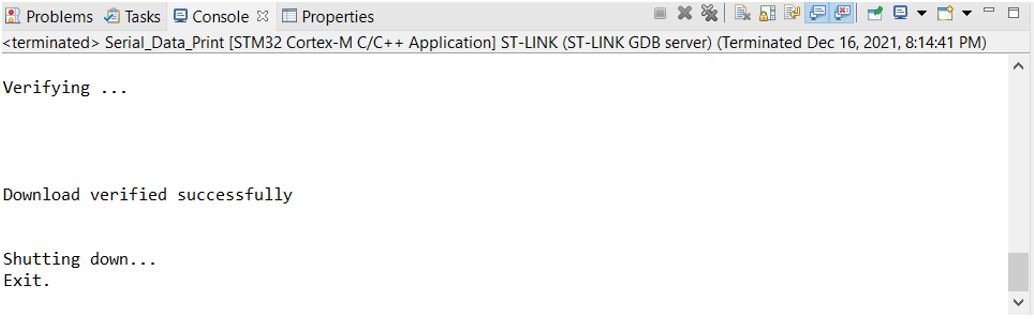
After a few moments, the code will be successfully sent to the STM32 board.
Otherwise, press the RESET button on your STM32
Hardware Setup for STM32 Nucleo Digital Counter
For this project we will require the following components:
- STM32 Nucleo
- One 10k resistor
- One Push button
- Connecting Wires
- Breadboard
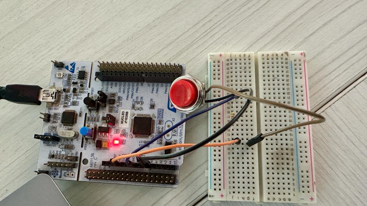
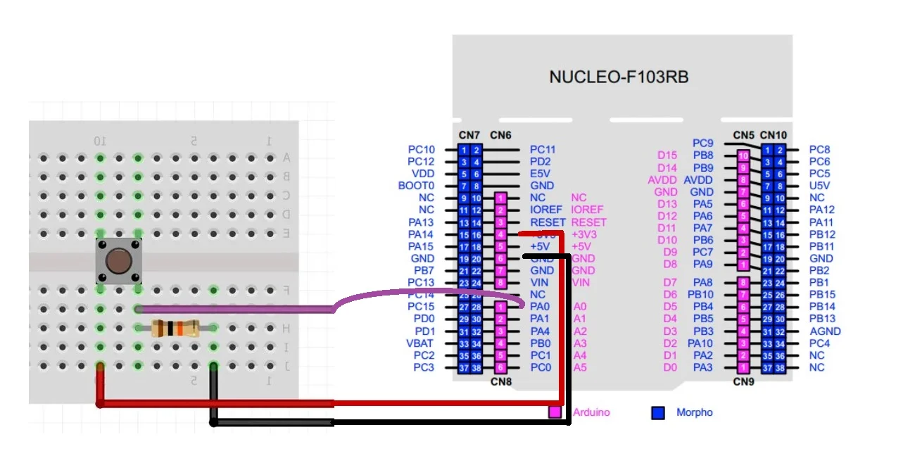
Connect the components as shown in the schematic diagram below:

Connect of end of the push button with PA0 through a 10k ohm (pull-down) resistor which is grounded at the other end. Another end of the push button will be connected with 3.3V pin from STM32 to power it up.
Demonstration
- Now connect your Nucleo with your computer via the USB port.
- Next press the RUN button in the IDE. The ‘Edit configuration’ window will open up. Click ‘OK’.
- After a few moments, the code will be successfully sent to the STM32 board. Otherwise, press the RESET button on your STM32 board.
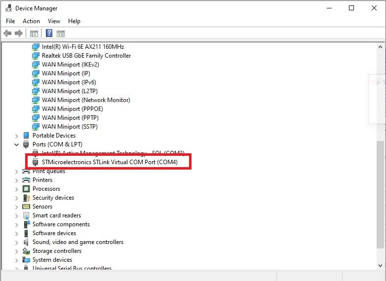
- Open Device Manager and head over to Ports to check the COM port through which the USB-TTL converter is connected. It is COM4 in our case.
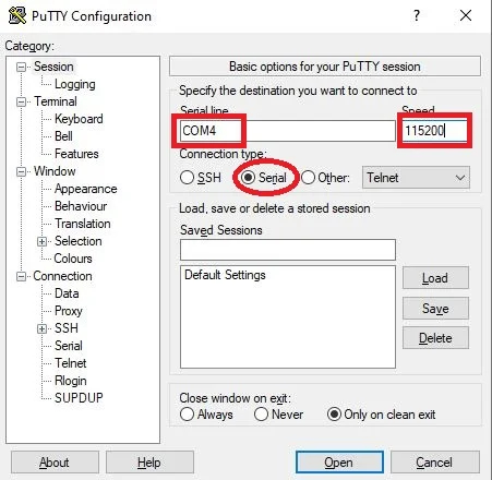
- Open a terminal on your system for example Putty. Set the correct speed and COM port and then press Open to establish a connection.
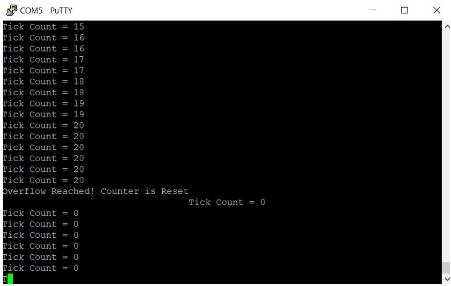
Press the Reset button of STM32. The tick count will be zero. Now press the push button and the tick count increases. It will increase with every rising edge of the input pin until it reaches 20. At this point, a new message gets displayed showing that an overflow occurred and the timer gets restarted from 0 again.
Conclusion
In conclusion, this user guide has demonstrated how to configure the STM32 Nucleo timer module in counter mode, specifically using the input edge capture method. By setting up the timer to count external events on a GPIO pin, we have effectively utilized the STM32CubeIDE and HAL libraries to implement a versatile counter. This configuration is useful for applications requiring event counting, such as pulse counting, encoder inputs, or monitoring external signals, making it a powerful feature in embedded system development with STM32 Nucleo boards.
You may also like to read:
- STM32 Nucleo Timer Encoder Mode with Rotary Encoder Example
- STM32 Nucleo Generate PWM with Timers using STM32CubeIDE
- STM32 Nucleo Timer Input Capture Mode with Frequency Measurement Example
- STM32 Nucleo Timer Interrupt with STM32CubeIDE and HAL Libraries
- GPIO External Interrupts STM32 Nucleo with STM32CubeIDE