In this guide, we will learn about KY-026 flame sensor and use it with Arduino for fire detection. By the end of this article, you will be able to know about the introduction of the flame sensor, its working principle, features, and pinout. Additionally, we will be able to interface the flame sensor with Arduino and program it for fire detection easily.
The flame sensor is used to detect fire or other light sources which are in the range of wavelength from 760nm to 1100nm. The module consists of an IR sensor, potentiometer, OP-Amp circuitry, and a led indicator. When a flame will be detected, the module will turn on its red led. This module is sensitive to flame but it can also detect ordinary light. The detection point is 60 degrees. The sensitivity of this sensor is adjustable and it also has stable performance.
It has both outputs, analog and digital. The analog output gives us a real-time voltage output signal on thermal resistance while the digital output allows us to set a threshold via a potentiometer. In our tutorial, we are going to use both of these outputs one by one and see how the sensor works.
We can use the flame sensor to make an alarm when detecting the fire, for safety purposes in many projects and in many more ways.
Flame or Fire Sensor Introduction
There are many types of flame sensors available in the market but we will use IR infrared flame sensor module in this tutorial. A picture of this flame sensor is shown below. As you can see in the picture, the main component of this sensor is an IR receiver that is a photodiode. This photodiode is used to detect flame and fire.

Working Principle
Whenever, a flame emits or a fire burns in the surrounding, it emits small amounts of infrared lights. This infrared light is used to detect flame or fire by this IR based flame sensor. Flame sensor IR receiver collects these IR waves which are emitted due to the fire burning. This IR receiver is connected with operation amplifier which provides the output in the form of voltage at the output of this sensor. We will simply connect this output with Arduino and process this information to turn on an LED which we will connect with our board as an output. So whenever fire or flame is detected around the flame sensor, the digital output pin DO goes high and when no fire is detected the output pin D0 will give logic low or zero volt.
Features
The flame sensor module has the following features:
- The operating voltage is from 3.3 – 5V.
- It gives us both analog and digital output.
- It has a led indicator, which indicates whether the flame is detected or not.
- The threshold value can be changed by rotating the top of a potentiometer.
- Flame detection distance, lighter flame test can be triggered within 0.8m. If the intensity of flame is high, the detection distance will be increased.
- The detection angle of the flame sensor module is about 60 degrees.
Flame Sensor Pinout
As shown in the above diagram. It has four pins. The functionality of each pin is given below:
- VCC pin: It is a power supply pin. The operating voltage of this sensor is 3.3 volt to 5 volt. But I recommend you to connect 5 volt to this pin to avoid any compatibility issues with the microcontroller.
- Ground pin: you should connect this pin with ground terminal of the microcontroller.
- A0 pin: It is an analog voltage output pin. Voltage across this pin varies according to intensity of fire or flame. But if you are designing only a fire detector circuit using this flame sensor then it is recommended to use the other output pin (D0).
- D0 pin: This is a digital output pin.
Fire Sensor Interfacing with Arduino
We will be requiring the following components in this project.
- Arduino UNO
- Infrared Fire Sensor (KY-026)
- Breadboard
- Connecting Wires
We will show you how to interface Arduino with the flame sensor using both the digital pin (DO) and the analog pin (AO).
Flame sensor interfacing with Arduino using the digital pin
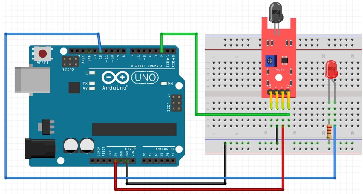
If using the digital pin, assemble the devices as shown in the schematic diagram below:

We will connect 3 pins of the KY-026 fire sensor module with Arduino. These include VCC, GND, and DO pins. The VCC pin will be connected with the 5V pin from Arduino. GND of both the devices will be in common. We will connect Arduino digital pin 2 with DO. We can change the threshold value of the sensor when using the digital pin by rotating the top of potentiometer.
For the LED, we have connected Arduino pin 12 with the anode pin, and the cathode pin is connected with the common ground through the 220 ohm resistor. When the sensor will detect a flame, then this LED will light up.
You can use appropriate digital pins of Arduino to connect with the fire sensor’s DO and the anode pin of the LED.
Flame sensor interfacing with Arduino using the analog pin
If using the analog pin, assemble the devices as shown in the schematic diagram below:

We will connect 3 pins of the KY-026 fire sensor module with Arduino. These include VCC, GND, and AO pins. The VCC pin will be connected with the 5V pin from Arduino. GND of both the devices will be in common. We will connect Arduino analog pin A0 with AO pin of the sensor.
For the LED, we have connected Arduino pin 12 with the anode pin, and the cathode pin is connected with the common ground through the 220 ohm resistor. When the sensor will detect a flame, then this LED will light up.
When using the analog pin of the Arduino, the Arduino will read from the sensor and give us values from 0 to 1023. We will further use these values and apply conditions to turn the LED ON/OFF.
Arduino Sketch for KY-026 Fire Detector using digital pin
Open your Arduino IDE and go to File > New to open a new file. Copy the code given below in that file.
int led_pin = 12;  // initializing the pin 12 as the led pin
int flame_sensor_pin = 2;   // initializing pin 2 as the sensor output pin
int flame_pin;    // state of sensor

void setup( ) {
  pinMode(led_pin , OUTPUT);    // declaring led pin as output pin
  pinMode(flame_sensor_pin , INPUT);   // declaring sensor pin as input pin for Arduino
  Serial.begin(9600);    // setting baud rate at 9600
}

void loop ( ) {
  flame_pin = digitalRead(flame_sensor_pin);  // reading from the sensor
  if (flame_pin == HIGH)          // applying condition
  {
    Serial.println("FIRE DETECTED!");
    digitalWrite(led_pin, HIGH); // if sensor state is high, then turn the led high
  }
  else
  {
    Serial.println("No Fire");
    digitalWrite(led_pin, LOW);    // otherwise turn it low
  }
  delay(1000);
}
How the Code Works?
The first step is to define the Arduino pins that we have connected with the sensor’s DO pin and the LED.
int led_pin = 12;
int flame_sensor_pin = 2;
Initially, set the state of the flame_pin to LOW. This means no fire is detected near the sensor.
int flame_pin = LOW;Inside the setup() function, we will open the serial communication at a baud rate of 9600. We will configure the sensor pin as an input pin and the LED pin as an output pin.
void setup( )   {
    pinMode(led_pin ,OUTPUT) ;                       // declaring led pin as output pin
    pinMode(flame_sensor_pin ,INPUT) ;              // declaring sensor pin as input pin for Arduino
    Serial.begin(9600) ;                            // setting baud rate at 9600
}
loop()
Inside the infinite loop() function, we will first find out the sensor output value using digitalRead(). We will pass the digital pin connected to the sensor as an argument inside it. This will be stored in the integer variable ‘flame_pin’.
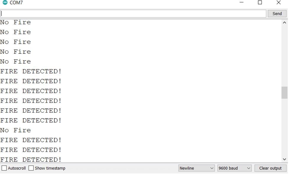
flame_pin = digitalRead(flame_sensor_pin); Then, we will check if the sensor output is HIGH or not. Remember the output will be HIGH whenever fire will be detected. If the output is indeed HIGH then the serial monitor will display “FIRE DETECTED!” and the LED will turn ON. However, if the state of the sensor output remains LOW then it means there is no fire nearby and “No Fire” message is printed in the serial monitor. Consequently, the LED is turned OFF.
  if (flame_pin == HIGH)          // applying condition
  {
    Serial.println("FIRE DETECTED!");
    digitalWrite(led_pin, HIGH); // if sensor state is high, then turn the led high
  }
  else
  {
    Serial.println("No Fire");
    digitalWrite(led_pin, LOW);    // otherwise turn it low
  }
  delay(1000);
Demonstration
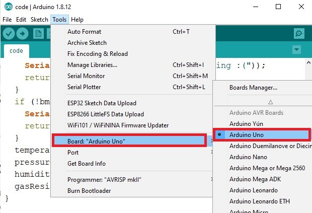
To see the demonstration of the above code, upload the code to Arduino. But, before uploading code, make sure to select the Arduino board from Tools > Board and also select the correct COM port to which the Arduino board is connected from Tools > Port.

In your Arduino IDE, open up the serial monitor and set the baud rate to 9600. Now bring a fire source close to the fire sensor and immediately the LED will turn ON. The serial monitor will also display relevant messages.

So this flame sensor can be used for fire detection. We can also set the range of flame sensor detection. It is very easy to detect flame or fire with the help of this little module. We can extend this project with home automation project and home security based project as well.
Arduino Sketch for KY-026 Fire Detector using an analog pin
Open your Arduino IDE and go to File > New to open a new file. Copy the code given below in that file.
int flame_Sensor_pin = A0; // initializing A0 as sensor pin
int Led_pin = 12; // initializing pin 12 as led pin
int Value = 0; // initializing a variable to store sensor value

void setup( ) {
  pinMode(Led_pin, OUTPUT); // declaring pin 12 as output pin
  Serial.begin(9600);      // Setting baud rate at 9600
}

void loop ( ) {
  Value = analogRead(flame_Sensor_pin); // reading from the sensor
  Serial.println(Value); // print analog value to serial
  delay(100);
  if (Value < 100) {
    digitalWrite(Led_pin, HIGH);
  }
  else {
    digitalWrite(Led_pin, LOW);
  }
}
How Does the Code Works?
The first step is to define the Arduino pins that we have connected with the sensor’s AO pin and the LED.
int flame_Sensor_pin = A0; // initializing A0 as sensor pin
int Led_pin = 12; // initializing pin 12 as led pin
Create an int variable called ‘value ‘ to store the sensor analog value. Initially, it is set to 0. The analog value will vary between 0-1023.
int Value = 0;Inside the setup() function, we will open the serial communication at a baud rate of 9600. We will configure the LED pin as an output pin.
void setup( ) {
  pinMode(Led_pin, OUTPUT); // declaring pin 12 as output pin
  Serial.begin(9600);      // Setting baud rate at 9600
}
loop()
Inside the infinite loop() function, we will first find out the sensor’s analog reading using analogRead(). We will pass the analog pin connected to the sensor as an argument inside it. This will be stored in the integer variable ‘Value’.
Value = analogRead(flame_Sensor_pin);Display the analog reading in the serial monitor/plotter after every second.
Serial.println(Value);
delay(100);
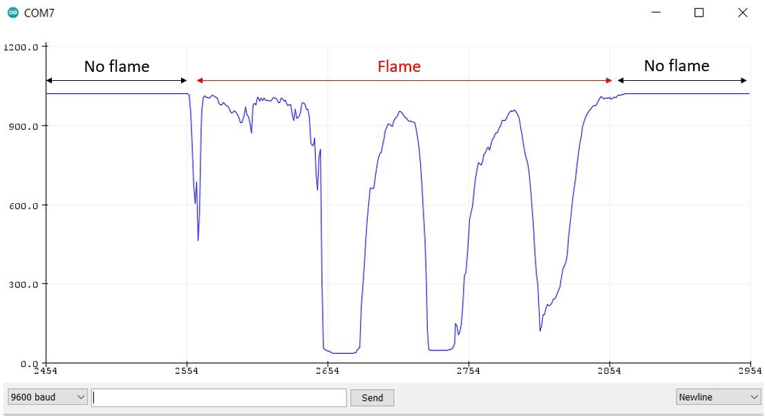
Remember the analog reading will vary between 0-1023. A higher reading indicates no flame or flame further away from the sensor. A lower reading indicates flame is closer to the sensor.
Then, if the analog value is less than 100, turn the LED ON. Otherwise, turn the LED OFF.
if (Value < 100) {
    digitalWrite(Led_pin, HIGH);
  }
  else {
    digitalWrite(Led_pin, LOW);
  }
Demonstration
To see the demonstration of the above code, upload the code to Arduino. But, before uploading code, make sure to select the Arduino board from Tools > Board and also select the correct COM port to which the Arduino board is connected from Tools > Port.

Once the code is uploaded to Arduino, open your serial plotter and set its baud rate to 9600. With no flame, the analog reading will be higher and closer to 1000. When flame is brought closer to the sensor the readings decrease abruptly. The LED turns ON if the readings are below 100.

see this video demo:
You may also like to read:


its amazing, just continue sending more
Can you pls suggest a way to reduce the sensitivity of flame sensor towards sun light
Mohammad Rashid, I think the potentiometer mitght change the sensitivity of flame sensor
it was rellay good project to make fire alarm circuit and i used this circuit in my home kitchen some times automatically the buzzer rangs without any flame why the problem was occuring i dont know but anyway this circuit was really help for me thank you