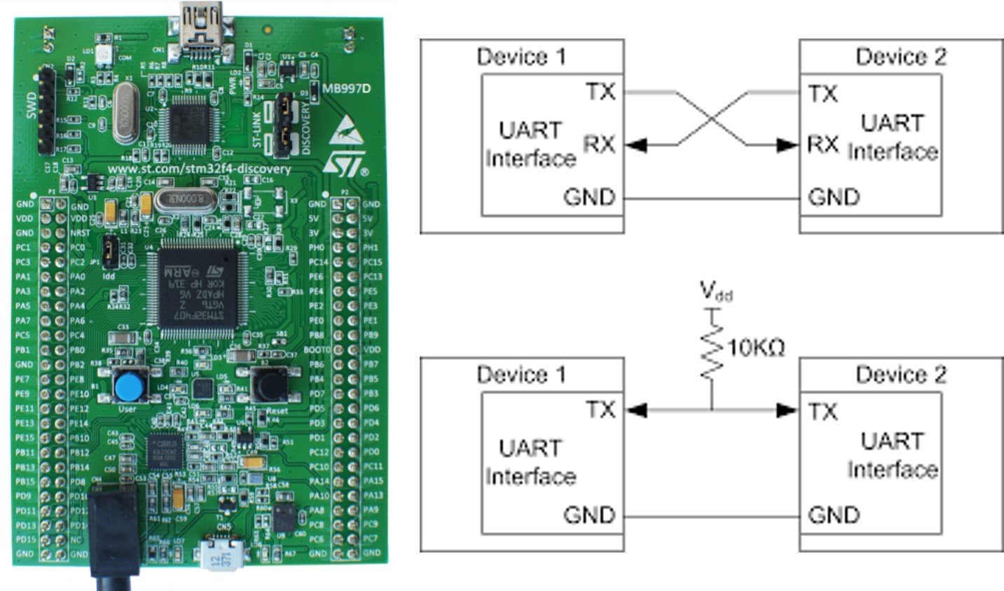
In this tutorial, we will learn to use UART communication ports of STM32F4 discovery board with the polling method. As you know, the STM32F4 discovery board comes with an STM32F407VG6T microcontroller. Like other STM32 family microcontrollers, this SoC also supports UART communication ports. STM32F407VG6T has on-chip 4 USARTs/2 UARTs communication channels. Each UART channel shares general-purpose input-output pins to transmit and receive data to/from external UART based devices. That means Rx and Tx pins of each UART port have shared alternate functions with GPIO pins. In short, an STM32F4 discovery board supports 8 UART/USART communication channels.
Why use the UART Port of the STM32F4 Discovery Board?
Whenever we work on embedded system applications development sooner or later we need to use a serial communication protocol. We often use UART/USAT transfer data between microcontroller and computer for various purposes. One of the most important applications is to display data on the serial console of the computer for debugging or logging important events during program execution on a microcontroller. Furthermore, many wireless devices such as GSM, GPS, Bluetooth, Xbee, LoRA, and many others provide a serial interface to transfer data between these devices and a microcontroller.
In the last tutorials, we have seen how to use STM32F4 GPIO pins as digital output or digital input pins. You can read these articles on these links:
For programming STM32F4 discovery board, we will use Keil Keil uvision. If you are a newbie with Keil uvision, you can take a look into these getting started guide:
Furthermore, we will use HAL Libraries and HAL UART drivers to write code for STM32F4 UART ports. Now let’s begin with an introduction of STM32F4 UART modules by looking into their features and specifications.
STM32F4 Discovery Board UART Introduction
This tutorial focuses on how to use UART communication ports of STM32F4 discovery board. We are not going into in-depth details of UART communication protocol itself. If you want to learn about this serial concepts such as frame format, pins, baud rate, synchronization, parity and odd bits, you can read this article:
Now let’s discuss the UART hardware block of STM32F4 discovery board. If you see the reference manual of STM32F407VG6T microcontroller and open the UART communication section, you will find that this microcontroller supports both synchronous and asynchronous data transfer. But in this tutorial, we are only going to discuss asynchronous mode that is UART.
There are four pins for communication. Two pins are used to transmit and receive data such as Tx and Rx pins. Because UART supports full-duplex communication. That means we can send and receive data simultaneously using Tx and Rx pins. If you check the block diagram of the UART module, there are separate registers for transmission and reception such as data transmit register (TDR) and data receive register (RDR). Further, both these registers have separate shift registers which are used to transmit and receive data bit by bit.

Other two pins are hardware flow control pins such as nRTC and nCTS. But we usually don’t use hardware flow control pins for microcontrollers to communicate with other microcontrollers or other devices.
UART Communication Between Two devices
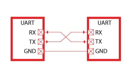
To perform UART communication between two devices, we Rx and Tx pins of devices with each other in inverse connection. For example, we want to share data between the STM32F4 discovery board and Arduino over a serial port. To accomplish this, we will connect an Rx pin of the discovery board with the Tx pin of Arduino and similarly, the Tx pin of the discovery board with the Rx pin of Arduino. Furthermore, the ground terminal of both devices should be connected to each other as shown in the diagram below:
UART Port Pins
As we mentioned earlier, STM32F407VG microcontroller provides 4 USART and 2 UART communication ports. The following table shows the GPIO pins corresponding to each communication port Tx/Rx pins and the bus to which USART module is connected and through which a clock is provided to each port.
| U(S)ARTx | TX | RX | TX | RX | TX | RX | APB |
|---|---|---|---|---|---|---|---|
| USART1 | PA9 | PA10 | PB6 | PB7 | 2 | ||
| USART2 | PA2 | PA3 | PD5 | PD6 | 1 | ||
| USART3 | PB10 | PB11 | PC10 | PC11 | PD8 | PD9 | 1 |
| UART4 | PA0 | PA1 | PC10 | PC11 | 1 | ||
| UART5 | PC12 | PD2 | 1 | ||||
| USART6 | PC6 | PC7 | PG14 | PG9 | 2 |
USART1 and USART6 are connected APB2 bus and ABP2 BUS can run at maximum of 84MHz. Therefore, maximum operating frequency for USART1 and USART6 is 84MHz.
But when the microcontroller is powered by an internal RC oscillator of 16MHz, the maximum peripheral clock your USART hardware gets is 16MHz. Because all the bus interfaces will be running at that speed. Similarly, USART2, UART3, UART4 and UART5 are connected to the APB1 bus whose maximum frequency is 42MHz. So the conclusion is that USART1 and 6 have the potential to run at higher frequencies than USART2, USART3, UART4 and UART5, since
They are on different buses. In this tutorial, we will use an internal RC oscillator, all USART hardware run with a peripheral frequency of 16.
Note: This peripheral frequency will be used by the baud rate generation block of the USART peripheral to produce different baud rates.
STM32F4 UART HAL Library Functions
As mentioned earlier, we will learn to use USART/UART channels of STM32F4 in polling mode which is also known as Blocking mode. Therefore, we will discuss blocking mode APIs and functions of UART HAL drivers in this section.
UART Data Transfer Modes
USART/UART channels of STM32F4 supports two modes of data transfer:
- Blocking mode: The communication is performed in polling mode. The HAL status of all data processing is returned by the same function after finishing transfer.
- Non-Blocking mode: The communication is performed using Interrupts or DMA, these API’s return the HAL status. The end of the data processing will be indicated through the dedicated UART IRQ when using Interrupt mode or the DMA IRQ when using DMA mode.
HAL UART Structures
Now let’s discuss two important C structures that are used to configure and manage UART/USART channels of an STM32F4 series of microcontrollers. The first important C struct is a UART_HandleTypeDef which is used to initialize a selected UART channel.
typedef struct
{
  uint32_t BaudRate;                  /*!< This member configures the UART communication baud rate.
                                           The baud rate is computed using the following formula:
                                           - IntegerDivider = ((PCLKx) / (8 * (OVR8+1) * (huart->Init.BaudRate)))
                                           - FractionalDivider = ((IntegerDivider - ((uint32_t) IntegerDivider)) * 8 * (OVR8+1)) + 0.5
                                           Where OVR8 is the "oversampling by 8 mode" configuration bit in the CR1 register. */

  uint32_t WordLength;                /*!< Specifies the number of data bits transmitted or received in a frame.
                                           This parameter can be a value of @ref UART_Word_Length */

  uint32_t StopBits;                  /*!< Specifies the number of stop bits transmitted.
                                           This parameter can be a value of @ref UART_Stop_Bits */

  uint32_t Parity;                    /*!< Specifies the parity mode.
                                           This parameter can be a value of @ref UART_Parity
                                           @note When parity is enabled, the computed parity is inserted
                                                 at the MSB position of the transmitted data (9th bit when
                                                 the word length is set to 9 data bits; 8th bit when the
                                                 word length is set to 8 data bits). */

  uint32_t Mode;                      /*!< Specifies whether the Receive or Transmit mode is enabled or disabled.
                                           This parameter can be a value of @ref UART_Mode */

  uint32_t HwFlowCtl;                 /*!< Specifies whether the hardware flow control mode is enabled or disabled.
                                           This parameter can be a value of @ref UART_Hardware_Flow_Control */

  uint32_t OverSampling;              /*!< Specifies whether the Over sampling 8 is enabled or disabled, to achieve higher speed (up to fPCLK/8).
                                           This parameter can be a value of @ref UART_Over_Sampling */
} UART_InitTypeDef;
The second important C struct is a UART_InitTypeDef which is used to configure different settings of a select UART channel such as baud rate, word length, stop bits, parity bits, mode, hardware flow control, and sampling.
typedef struct __UART_HandleTypeDef
{
  USART_TypeDef                 *Instance;        /*!< UART registers base address        */

  UART_InitTypeDef              Init;             /*!< UART communication parameters      */

  uint8_t                       *pTxBuffPtr;      /*!< Pointer to UART Tx transfer Buffer */

  uint16_t                      TxXferSize;       /*!< UART Tx Transfer size              */

  __IO uint16_t                 TxXferCount;      /*!< UART Tx Transfer Counter           */

  uint8_t                       *pRxBuffPtr;      /*!< Pointer to UART Rx transfer Buffer */

  uint16_t                      RxXferSize;       /*!< UART Rx Transfer size              */

  __IO uint16_t                 RxXferCount;      /*!< UART Rx Transfer Counter           */

  DMA_HandleTypeDef             *hdmatx;          /*!< UART Tx DMA Handle parameters      */

  DMA_HandleTypeDef             *hdmarx;          /*!< UART Rx DMA Handle parameters      */

  HAL_LockTypeDef               Lock;             /*!< Locking object                     */

  __IO HAL_UART_StateTypeDef    gState;           /*!< UART state information related to global Handle management
                                                       and also related to Tx operations.
                                                       This parameter can be a value of @ref HAL_UART_StateTypeDef */

  __IO HAL_UART_StateTypeDef    RxState;          /*!< UART state information related to Rx operations.
                                                       This parameter can be a value of @ref HAL_UART_StateTypeDef */

  __IO uint32_t                 ErrorCode;        /*!< UART Error code                    */

#if (USE_HAL_UART_REGISTER_CALLBACKS == 1)
  void (* TxHalfCpltCallback)(struct __UART_HandleTypeDef *huart);        /*!< UART Tx Half Complete Callback        */
  void (* TxCpltCallback)(struct __UART_HandleTypeDef *huart);            /*!< UART Tx Complete Callback             */
  void (* RxHalfCpltCallback)(struct __UART_HandleTypeDef *huart);        /*!< UART Rx Half Complete Callback        */
  void (* RxCpltCallback)(struct __UART_HandleTypeDef *huart);            /*!< UART Rx Complete Callback             */
  void (* ErrorCallback)(struct __UART_HandleTypeDef *huart);             /*!< UART Error Callback                   */
  void (* AbortCpltCallback)(struct __UART_HandleTypeDef *huart);         /*!< UART Abort Complete Callback          */
  void (* AbortTransmitCpltCallback)(struct __UART_HandleTypeDef *huart); /*!< UART Abort Transmit Complete Callback */
  void (* AbortReceiveCpltCallback)(struct __UART_HandleTypeDef *huart);  /*!< UART Abort Receive Complete Callback  */
  void (* WakeupCallback)(struct __UART_HandleTypeDef *huart);            /*!< UART Wakeup Callback                  */

  void (* MspInitCallback)(struct __UART_HandleTypeDef *huart);           /*!< UART Msp Init callback                */
  void (* MspDeInitCallback)(struct __UART_HandleTypeDef *huart);         /*!< UART Msp DeInit callback              */
#endif  /* USE_HAL_UART_REGISTER_CALLBACKS */

} UART_HandleTypeDef;
HAL UART Initialization Function
HAL_UART_Init() function initializes the UART mode according to the specified parameters in the UART_InitTypeDef and creates the associated handle.
HAL_StatusTypeDef HAL_UART_Init(UART_HandleTypeDef *huart)
HAL UART Data Transmit Fucntion
In Polling mode IO operation of UART module of STM32F4, HAL_UART_Transmit() is used to send an amount of data in blocking mode HAL_UART_Receive() is used to receive an amount of data in blocking mode. These API’s are :
HAL_StatusTypeDef HAL_UART_Transmit(UART_HandleTypeDef *huart, uint8_t *pData, uint16_t Size, uint32_t Timeout)- First parameter huart is a pointer to a UART_HandleTypeDef structure that contains the configuration information for the specified UART module.
- Second parameter pData is a Pointer to data buffer that we want to transmit
- Third parameter is the amount of data elements (u8 or u16) to be sent
- Last parameter is a timeout duration for this function to retry.
- The return type of this function is a HAL status enum which contains status.
typedef enum
{
  HAL_OK       = 0x00U,
  HAL_ERROR    = 0x01U,
  HAL_BUSY     = 0x02U,
  HAL_TIMEOUT  = 0x03U
} HAL_StatusTypeDef;
HAL UART Data Receive Fucntion
It receives an amount of data in blocking mode on the selected UART channel recieve pin.
HAL_StatusTypeDef HAL_UART_Receive(UART_HandleTypeDef *huart, uint8_t *pData, uint16_t Size, uint32_t Timeout)
- First parameter huart is a pointer to a UART_HandleTypeDef structure that contains the configuration information for the specified UART module.
- Second parameter pData is a pointer to a data buffer in which we want to store received data
- Third parameter is the amount of data elements (u8 or u16) to be received
- Last parameter is a timeout duration for this function to retry.
- The return type of this function is a HAL status enum which contains status
STM32F4 UART Data Transmit Example
As discussed earlier, STM32F407VG6T microcontroller has 4 USART channels and 2 UART channels. That means 4 USART channels can also be used as UART channels only. But 2 UART modules cannot be used to transfer data synchronously.
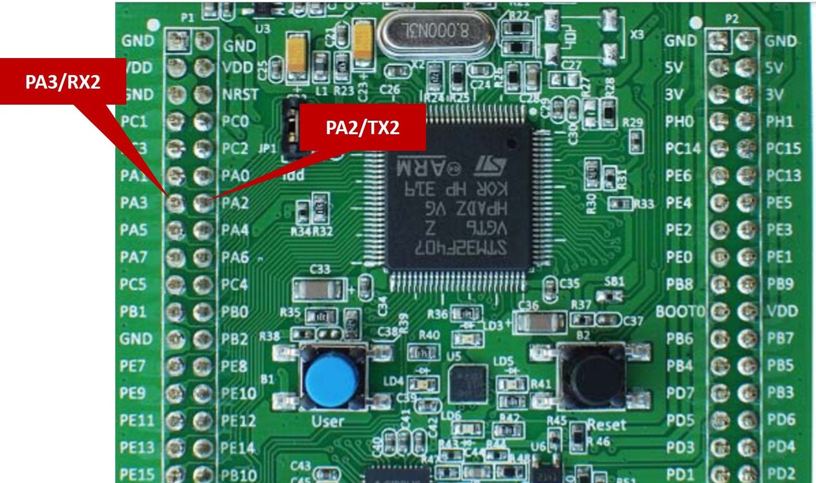
In this tutorial, we will use the USART2 channel in asynchronous mode. We can call it a UART2 channel when using asynchronous mode.

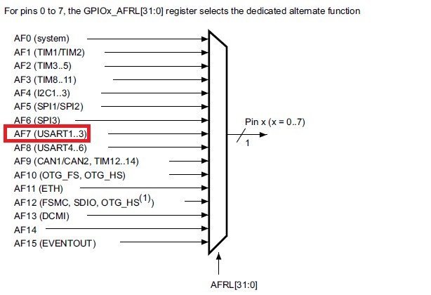
PA2 and PA3 pins of GPIOA are as alternative function pins for the UART2 channel as Tx2 and Rx2 pins, respectively. We can select the alternate function of PA2 and PA3 pins for the UART2 channel with the GPIOx_AFRL[31:0] register by selecting the AF7 bit a shown in this mapping diagram:
Code
This example code uses a UART2 channel in a polling method to transmit data on PA2 and PA3 GPIO pins. In the coming tutorial, we will learn to use STM32F4 UART in interrupt mode and with DMA. The following example code transmits a string “Welcome to Microcontrollers Lab\r\n” through HAL_UART_Transmit() function after every one second.
#include "stm32f4xx_hal.h"
#include <string.h>

/*Function prototype for delay and UART2 configuration functions */
void UART2_Configuration(void);
void Delay_ms(volatile int time_ms);

UART_HandleTypeDef UART_Handler; /*Create UART_HandleTypeDef struct instance */
char Message[] = "Welcome to Microcontrollers Lab\r\n"; /* Message to be transmitted through UART */

int main(void)
{
	HAL_Init(); /* HAL library initialization */
	UART2_Configuration(); /* Call UART2 initialization define below */
	while(1)
	{
		HAL_UART_Transmit(&UART_Handler, (uint8_t *)Message, strlen(Message), 10);
		Delay_ms(100);
	}
}

void UART2_Configuration(void)
{
	__HAL_RCC_GPIOA_CLK_ENABLE(); /* Enable clock to PORTA - UART2 pins PA2 and PA3 */
	__HAL_RCC_USART2_CLK_ENABLE(); /* Enable clock to UART2 module */

	GPIO_InitTypeDef UART2_GPIO_Handler; /*Create GPIO_InitTypeDef struct instance */
	UART2_GPIO_Handler.Pin = GPIO_PIN_2 | GPIO_PIN_3;
	UART2_GPIO_Handler.Mode = GPIO_MODE_AF_PP;
	UART2_GPIO_Handler.Pull = GPIO_PULLUP;
	UART2_GPIO_Handler.Speed = GPIO_SPEED_FREQ_VERY_HIGH;
	UART2_GPIO_Handler.Alternate = GPIO_AF7_USART2;
	HAL_GPIO_Init(GPIOA, &UART2_GPIO_Handler);
	//UART Configuration
	UART_Handler.Instance = USART2;
	UART_Handler.Init.BaudRate = 115200;
	UART_Handler.Init.Mode = UART_MODE_TX_RX;
	UART_Handler.Init.WordLength = UART_WORDLENGTH_8B;
	UART_Handler.Init.StopBits = UART_STOPBITS_1;
	UART_Handler.Init.OverSampling = UART_OVERSAMPLING_16;
	HAL_UART_Init(&UART_Handler);
}

void SysTick_Handler(void)
{
  HAL_IncTick();
  HAL_SYSTICK_IRQHandler();
}
/*Generate ms */
void Delay_ms(volatile int time_ms)
{
	      int j;
        for(j = 0; j < time_ms*4000; j++)
            {}  /* excute NOP for 1ms */
}
Demo
In order to see the demo of the above STM32F4 UART code (polling method), we use USB to serial converter FTDI cable. FTDI cable is used to transfer data to a computer through a USB port of a computer. For more information on FTDI cable and how to use it, read this tutorial:
Connect an FTDI cable with PA2 and PA3 PA3 pins of STM32F4 discovery board according to this connection diagram:

| STM32F4 Discovery Board | FTDI Cable |
|---|---|
| PA2/TX2 | Rx |
| PA3/RX2 | Tx |
| GND | GND |
Upload the code to the STM32F4 discovery board by clicking on the upload button on Keil Keil uvision IDE. If you don’t know how to create STM32F4 project in Keil vision, you can read this getting started guide:
After that open a serial terminal such as Putty on your computer by specifying the COM port number of an FTDI cable. You can check the COM port number for your FTDI cable from the device manager.

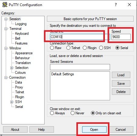
Now open the putty terminal and make settings according to this figure and click on open.
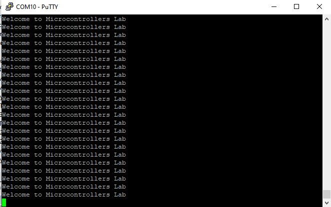
Now hit the reset button, you will see a welcome string on the serial console as shown in the figure below:
STM32F4 UART Receive Example
This example code receives a character on RX2 pin of STM32F4 discovery board and transmit back the same data through Tx2 pin.
Code
#include "stm32f4xx_hal.h"
#include <string.h>

/*Function prototype for delay and UART2 configuration functions */
void UART2_Configuration(void);
void Delay_ms(volatile int time_ms);

UART_HandleTypeDef UART_Handler; /*Create UART_HandleTypeDef struct instance */
char Message[] = "Write anything on Serial Terminal\r\n"; /* Message to be transmitted through UART */

int main(void)
{
	HAL_Init(); /* HAL library initialization */
	UART2_Configuration(); /* Call UART2 initialization define below */
	HAL_UART_Transmit(&UART_Handler, (uint8_t *)Message, strlen(Message), 10);
	while(1)
	{
		 uint8_t buffer[4];
     HAL_UART_Receive(&UART_Handler, buffer, sizeof(buffer), HAL_MAX_DELAY);
     HAL_UART_Transmit(&UART_Handler, buffer, sizeof(buffer), HAL_MAX_DELAY);
	}
}

void UART2_Configuration(void)
{
	__HAL_RCC_GPIOA_CLK_ENABLE(); /* Enable clock to PORTA - UART2 pins PA2 and PA3 */
	__HAL_RCC_USART2_CLK_ENABLE(); /* Enable clock to UART2 module */

	GPIO_InitTypeDef UART2_GPIO_Handler; /*Create GPIO_InitTypeDef struct instance */
	UART2_GPIO_Handler.Pin = GPIO_PIN_2 | GPIO_PIN_3;
	UART2_GPIO_Handler.Mode = GPIO_MODE_AF_PP;
	UART2_GPIO_Handler.Pull = GPIO_PULLUP;
	UART2_GPIO_Handler.Speed = GPIO_SPEED_FREQ_VERY_HIGH;
	UART2_GPIO_Handler.Alternate = GPIO_AF7_USART2;
	HAL_GPIO_Init(GPIOA, &UART2_GPIO_Handler);
	//UART Configuration
	UART_Handler.Instance = USART2;
	UART_Handler.Init.BaudRate = 115200;
	UART_Handler.Init.Mode = UART_MODE_TX_RX;
	UART_Handler.Init.WordLength = UART_WORDLENGTH_8B;
	UART_Handler.Init.StopBits = UART_STOPBITS_1;
	UART_Handler.Init.OverSampling = UART_OVERSAMPLING_16;
	HAL_UART_Init(&UART_Handler);
}

void SysTick_Handler(void)
{
  HAL_IncTick();
  HAL_SYSTICK_IRQHandler();
}
/*Generate ms */
void Delay_ms(volatile int time_ms)
{
	      int j;
        for(j = 0; j < time_ms*4000; j++)
            {}  /* excute NOP for 1ms */
}
Demo
Follow the same steps as mentioned above to open putty after uploading code to the STM32F4 discovery board. Now, type anything on the Putty terminal, it will be echo back to the terminal. In other words. Whatever you type on the Putty terminal, it will be sent to the STM32F4 discovery board and STM32F4 will transmit it back to the computer through UART transmit function.

In summary, we learned the following in this tutorial:
- STM32F4 UART Introduction
- HAL USART/UART Driver
- How to use STM32F4 UART in polling mode
Other STM32F4 Tutorials: