This STM32F4 Discovery Board UART tutorial teaches you how to use the UART/USART communication ports of the STM32F407VGT6 microcontroller in polling mode using the HAL UART driver in Keil uvision IDE. Serial communication is one of the most widely used peripherals in embedded systems — it’s how your microcontroller talks to a PC for debugging, how it sends AT commands to a GSM or Bluetooth module, and how most sensor breakout boards stream their data. By the end of this guide you will have a complete working UART example on the STM32F4 Discovery Board that both transmits and receives characters over a real serial terminal.
The STM32F407VGT6 is generous with serial ports. Like other STM32 family microcontrollers, it provides on-chip 4 USART and 2 UART channels — so eight UART/USART ports in total — each of which shares its Rx and Tx lines with specific GPIO pins via the alternate function multiplexer. This tutorial focuses on USART2 (pins PA2/PA3), but the same HAL pattern works on every other port with only a change of pin and instance.
What You Will Learn
- The difference between UART, USART, and synchronous vs asynchronous serial communication
- How the STM32F407VGT6 maps its 6 USART/UART channels to GPIO alternate functions
- Which USART peripherals sit on APB1 vs APB2 and why it matters for maximum baud rate
- The role of the
UART_HandleTypeDefandUART_InitTypeDefstructures in HAL UART configuration - How to configure baud rate, word length, stop bits, parity, mode, and oversampling
- How to use
HAL_UART_Transmit()andHAL_UART_Receive()in blocking (polling) mode - A complete example that transmits a welcome string from the STM32F4 over UART2
- A complete echo example that receives characters and sends them back
- How to wire an FTDI USB-to-serial cable to PA2/PA3 and view the output in PuTTY
- Common UART troubleshooting: wrong baud, swapped Tx/Rx, missing GND, encoding issues
Prerequisites and Required Components
- STM32F4 Discovery Board (STM32F407G-DISC1)
- FTDI USB-to-serial cable (or any 3.3 V USB-UART adapter like CP2102, CH340G) — this is what bridges the STM32 to your PC’s USB port
- 3 jumper wires for the Tx, Rx, and GND connections
- Mini USB cable for programming and power via the onboard ST-LINK/V2
- Keil uvision IDE with the STM32F4 device pack installed
- A serial terminal on your PC — PuTTY, Tera Term, or the Arduino IDE serial monitor all work
- Familiarity with the earlier tutorials in this STM32F4 series (LED blinking, push button, ADC, DAC) — this tutorial assumes you can already create a Keil project and configure GPIO pins using HAL
Important: the STM32F4 is a 3.3 V device. Your USB-to-serial adapter must also operate at 3.3 V logic. Using a 5 V FTDI cable can damage the STM32F4 Discovery Board’s GPIO pins.
Why Use the UART Port of the STM32F4 Discovery Board?
Whenever we work on embedded systems development, sooner or later we need a serial communication protocol. UART/USART is the simplest and most universal way to move data between a microcontroller and a PC — or between two microcontrollers — and it is the de facto debugging channel for almost every MCU on the market.
Common UART use cases on the STM32F4 Discovery Board include:
- Debugging — printing
printf()-style messages and sensor values to a PC terminal during development - Logging — streaming important events to a PC or SD card via a UART-to-SD bridge
- Wireless modules — GSM modems, GPS receivers, Bluetooth modules, XBee, LoRA, ESP8266, Wi-Fi modules, RFID readers — almost all expose a UART interface
- Sensor breakouts — air quality sensors (PMS5003), fingerprint scanners, LIDAR units, and many industrial sensors speak serial
- MCU-to-MCU communication — the simplest way to pass data between, say, an STM32F4 and an Arduino
In previous tutorials we learned how to use STM32F4 GPIO pins as digital outputs and inputs. For programming the STM32F4 Discovery Board we use Keil uvision. If you are new to Keil, the LED blinking and push button tutorials (linked above) walk through installation and project creation step by step.
In this UART tutorial we will use the HAL libraries and HAL UART driver to write code for the STM32F4’s UART ports. Let’s start with an overview of the UART hardware itself.
STM32F4 Discovery Board UART Introduction
This tutorial focuses on using the UART communication ports of the STM32F4 Discovery Board — it does not go deep into the UART protocol itself. If you want to learn the underlying concepts such as frame format, pin roles, baud rate, synchronization, parity bit, and stop bits, read our dedicated protocol article:
Now let’s discuss the UART hardware block inside the STM32F4 Discovery Board. If you open the STM32F407VG reference manual and look at the UART section, you will find that the peripheral supports both synchronous and asynchronous data transfer. The difference is simple: USART (Universal Synchronous/Asynchronous Receiver-Transmitter) can clock data with a shared clock line (synchronous), while UART (Universal Asynchronous Receiver-Transmitter) relies purely on pre-agreed baud rate and framing (asynchronous). In this tutorial we use asynchronous mode only — UART.
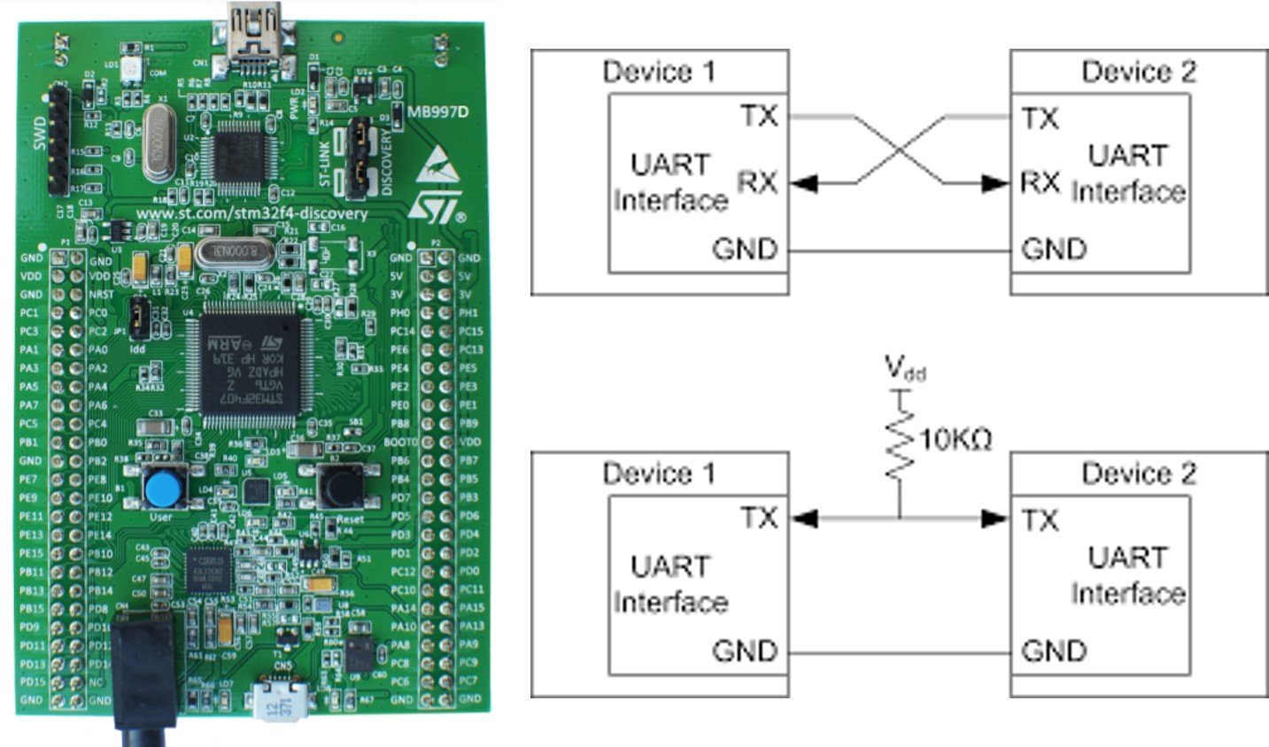
A UART link uses four signals, though only three are typically connected. Two pins carry data — Tx (transmit) and Rx (receive) — and UART is full-duplex, meaning the STM32F4 can send and receive data simultaneously over these two pins. If you check the block diagram of the UART module below, you will see separate registers for transmission and reception — the data transmit register (TDR) and data receive register (RDR) — and each has its own shift register that moves bits in and out one at a time at the configured baud rate.

The other two pins — nRTS (request to send) and nCTS (clear to send) — are hardware flow-control lines. For simple microcontroller-to-microcontroller or microcontroller-to-PC communication, flow control is almost never used and you can leave it disabled.
UART Communication Between Two Devices
To perform UART communication between two devices, the Rx and Tx pins cross over — the transmitter of one device connects to the receiver of the other. For example, to share data between the STM32F4 Discovery Board and an Arduino over a serial port, you connect the Rx pin of the Discovery Board to the Tx pin of the Arduino, and the Tx pin of the Discovery Board to the Rx pin of the Arduino. The ground terminals of both devices must also be connected together so they share a common reference, as shown in the diagram below:
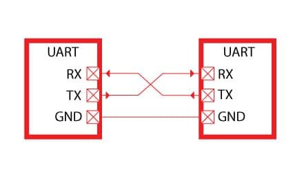
Never forget to connect the ground (GND) between the two UART devices. Without a common ground, the Tx/Rx voltage levels have no shared reference point and communication will either fail completely or appear to work intermittently, which is maddening to debug.
UART Port Pins on the STM32F4 Discovery Board
As mentioned earlier, the STM32F407VG microcontroller provides 4 USART and 2 UART communication ports. The table below shows the GPIO pin options for each Tx/Rx line and which APB bus the peripheral clock comes from. Many ports have two or three alternate pin options, which is useful when another peripheral is already using one of the options.
| U(S)ARTx | TX | RX | TX | RX | TX | RX | APB |
|---|---|---|---|---|---|---|---|
| USART1 | PA9 | PA10 | PB6 | PB7 | 2 | ||
| USART2 | PA2 | PA3 | PD5 | PD6 | 1 | ||
| USART3 | PB10 | PB11 | PC10 | PC11 | PD8 | PD9 | 1 |
| UART4 | PA0 | PA1 | PC10 | PC11 | 1 | ||
| UART5 | PC12 | PD2 | 1 | ||||
| USART6 | PC6 | PC7 | PG14 | PG9 | 2 |
USART1 and USART6 sit on the APB2 bus, which can run up to 84 MHz on a fully-clocked STM32F4. This means USART1 and USART6 can achieve higher maximum baud rates than the other ports.
However, if the microcontroller is powered by the internal RC oscillator (16 MHz, the default after reset), every peripheral clock is effectively 16 MHz and the baud rate advantage of APB2 disappears. USART2, USART3, UART4, and UART5 are on the APB1 bus, which has a maximum of 42 MHz. So when the MCU clock tree is configured for maximum performance, USART1 and USART6 run twice as fast as the APB1 ports — but in this tutorial we use the internal 16 MHz oscillator for simplicity, so all UART hardware runs at 16 MHz.
Note: This peripheral frequency is what the USART’s baud rate generator divides down to produce the configured baud rate (9600, 115200, etc.). Higher peripheral clocks give better baud rate accuracy, which becomes important at high speeds like 921600 baud.
STM32F4 UART HAL Library Functions
We will use the USART/UART channels of the STM32F4 in polling mode (also called blocking mode). In polling mode the CPU sits inside the HAL transmit or receive call until the transfer is complete or a timeout expires. It is the simplest mode to understand and the right starting point — interrupt mode and DMA mode are covered in later tutorials.
UART Data Transfer Modes
The USART/UART channels of the STM32F4 support two transfer modes:
- Blocking mode (polling): the CPU stays inside the HAL call until the data has been transmitted or received. Simple, but wastes CPU cycles during the transfer.
- Non-blocking mode (interrupts or DMA): the HAL call returns immediately and a callback fires when the transfer finishes (UART IRQ for interrupt mode, DMA IRQ for DMA mode). More efficient and essential for high-throughput or low-latency applications.
HAL UART Structures
Two important C structures are used to configure and manage UART/USART channels on the STM32F4. The first is UART_InitTypeDef, which holds all the per-port configuration settings — baud rate, word length, stop bits, parity, mode, hardware flow control, and oversampling.
typedef struct
{
  uint32_t BaudRate;                  /*!< This member configures the UART communication baud rate.
                                           The baud rate is computed using the following formula:
                                           - IntegerDivider = ((PCLKx) / (8 * (OVR8+1) * (huart->Init.BaudRate)))
                                           - FractionalDivider = ((IntegerDivider - ((uint32_t) IntegerDivider)) * 8 * (OVR8+1)) + 0.5
                                           Where OVR8 is the "oversampling by 8 mode" configuration bit in the CR1 register. */

  uint32_t WordLength;                /*!< Specifies the number of data bits transmitted or received in a frame.
                                           This parameter can be a value of @ref UART_Word_Length */

  uint32_t StopBits;                  /*!< Specifies the number of stop bits transmitted.
                                           This parameter can be a value of @ref UART_Stop_Bits */

  uint32_t Parity;                    /*!< Specifies the parity mode.
                                           This parameter can be a value of @ref UART_Parity
                                           @note When parity is enabled, the computed parity is inserted
                                                 at the MSB position of the transmitted data (9th bit when
                                                 the word length is set to 9 data bits; 8th bit when the
                                                 word length is set to 8 data bits). */

  uint32_t Mode;                      /*!< Specifies whether the Receive or Transmit mode is enabled or disabled.
                                           This parameter can be a value of @ref UART_Mode */

  uint32_t HwFlowCtl;                 /*!< Specifies whether the hardware flow control mode is enabled or disabled.
                                           This parameter can be a value of @ref UART_Hardware_Flow_Control */

  uint32_t OverSampling;              /*!< Specifies whether the Over sampling 8 is enabled or disabled, to achieve higher speed (up to fPCLK/8).
                                           This parameter can be a value of @ref UART_Over_Sampling */
} UART_InitTypeDef;
The second structure is UART_HandleTypeDef, which represents an individual UART peripheral instance. It bundles the register base, the UART_InitTypeDef settings, transmit and receive buffer pointers, DMA handles, lock state, and error codes. Almost every HAL UART function takes a pointer to a UART_HandleTypeDef.
typedef struct __UART_HandleTypeDef
{
  USART_TypeDef                 *Instance;        /*!< UART registers base address        */

  UART_InitTypeDef              Init;             /*!< UART communication parameters      */

  uint8_t                       *pTxBuffPtr;      /*!< Pointer to UART Tx transfer Buffer */

  uint16_t                      TxXferSize;       /*!< UART Tx Transfer size              */

  __IO uint16_t                 TxXferCount;      /*!< UART Tx Transfer Counter           */

  uint8_t                       *pRxBuffPtr;      /*!< Pointer to UART Rx transfer Buffer */

  uint16_t                      RxXferSize;       /*!< UART Rx Transfer size              */

  __IO uint16_t                 RxXferCount;      /*!< UART Rx Transfer Counter           */

  DMA_HandleTypeDef             *hdmatx;          /*!< UART Tx DMA Handle parameters      */

  DMA_HandleTypeDef             *hdmarx;          /*!< UART Rx DMA Handle parameters      */

  HAL_LockTypeDef               Lock;             /*!< Locking object                     */

  __IO HAL_UART_StateTypeDef    gState;           /*!< UART state information related to global Handle management
                                                       and also related to Tx operations.
                                                       This parameter can be a value of @ref HAL_UART_StateTypeDef */

  __IO HAL_UART_StateTypeDef    RxState;          /*!< UART state information related to Rx operations.
                                                       This parameter can be a value of @ref HAL_UART_StateTypeDef */

  __IO uint32_t                 ErrorCode;        /*!< UART Error code                    */

#if (USE_HAL_UART_REGISTER_CALLBACKS == 1)
  void (* TxHalfCpltCallback)(struct __UART_HandleTypeDef *huart);        /*!< UART Tx Half Complete Callback        */
  void (* TxCpltCallback)(struct __UART_HandleTypeDef *huart);            /*!< UART Tx Complete Callback             */
  void (* RxHalfCpltCallback)(struct __UART_HandleTypeDef *huart);        /*!< UART Rx Half Complete Callback        */
  void (* RxCpltCallback)(struct __UART_HandleTypeDef *huart);            /*!< UART Rx Complete Callback             */
  void (* ErrorCallback)(struct __UART_HandleTypeDef *huart);             /*!< UART Error Callback                   */
  void (* AbortCpltCallback)(struct __UART_HandleTypeDef *huart);         /*!< UART Abort Complete Callback          */
  void (* AbortTransmitCpltCallback)(struct __UART_HandleTypeDef *huart); /*!< UART Abort Transmit Complete Callback */
  void (* AbortReceiveCpltCallback)(struct __UART_HandleTypeDef *huart);  /*!< UART Abort Receive Complete Callback  */
  void (* WakeupCallback)(struct __UART_HandleTypeDef *huart);            /*!< UART Wakeup Callback                  */

  void (* MspInitCallback)(struct __UART_HandleTypeDef *huart);           /*!< UART Msp Init callback                */
  void (* MspDeInitCallback)(struct __UART_HandleTypeDef *huart);         /*!< UART Msp DeInit callback              */
#endif  /* USE_HAL_UART_REGISTER_CALLBACKS */

} UART_HandleTypeDef;
HAL UART Initialization Function
The HAL_UART_Init() function initializes a UART channel according to the parameters inside the UART_InitTypeDef structure and creates the associated handle.
HAL_StatusTypeDef HAL_UART_Init(UART_HandleTypeDef *huart)HAL UART Data Transmit Function
In polling (blocking) mode, HAL_UART_Transmit() sends a buffer of data out of the UART Tx pin, while HAL_UART_Receive() reads a buffer from the UART Rx pin. Both return a HAL_StatusTypeDef value indicating success, error, busy, or timeout.
HAL_StatusTypeDef HAL_UART_Transmit(UART_HandleTypeDef *huart, uint8_t *pData, uint16_t Size, uint32_t Timeout)- First argument
huartis a pointer to aUART_HandleTypeDefstructure containing the configuration of the UART module you want to use. - Second argument
pDatais a pointer to the data buffer to transmit. - Third argument is the number of data elements (8-bit or 16-bit) to send.
- Fourth argument is the timeout in milliseconds — the function returns with
HAL_TIMEOUTif the transfer doesn’t finish in time. - The return type is a
HAL_StatusTypeDefenum value.
typedef enum
{
  HAL_OK       = 0x00U,
  HAL_ERROR    = 0x01U,
  HAL_BUSY     = 0x02U,
  HAL_TIMEOUT  = 0x03U
} HAL_StatusTypeDef;
HAL UART Data Receive Function
HAL_UART_Receive() reads a specified amount of data in blocking mode from the UART Rx pin of the selected channel.
HAL_StatusTypeDef HAL_UART_Receive(UART_HandleTypeDef *huart, uint8_t *pData, uint16_t Size, uint32_t Timeout)
- First argument
huartis a pointer to aUART_HandleTypeDefstruct containing the UART configuration. - Second argument
pDatais a pointer to the data buffer where received bytes will be stored. - Third argument is the number of data elements (8-bit or 16-bit) to receive.
- Fourth argument is the timeout duration in milliseconds.
- The return type is a
HAL_StatusTypeDefenum value.
STM32F4 UART Data Transmit Example
As discussed earlier, the STM32F407VGT6 microcontroller has 4 USART channels and 2 UART channels. The USART channels can also be used as plain UART (just ignore the synchronous-mode features), but the 2 dedicated UART modules cannot transfer data synchronously.
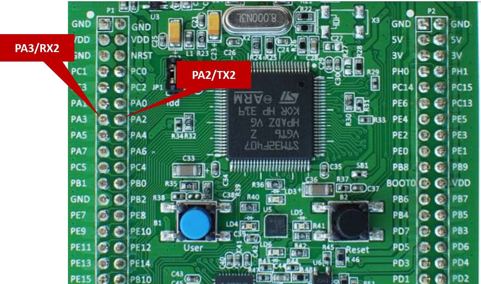
In this tutorial we will use the USART2 channel in asynchronous mode — so we can call it UART2.

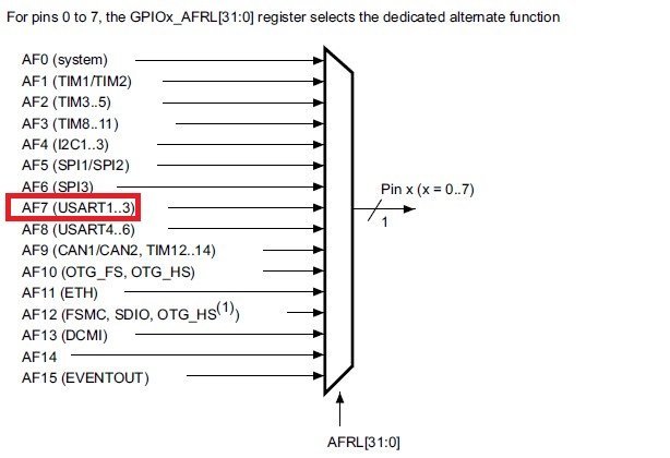
PA2 and PA3 of GPIOA are the alternate function pins for UART2 — PA2 is Tx2 and PA3 is Rx2. To route PA2/PA3 to the UART2 peripheral instead of acting as plain GPIO, we select alternate function AF7 via the GPIOx_AFRL register, as shown in the mapping diagram below:
Complete STM32F4 UART2 Transmit Code
This example uses UART2 in polling mode to transmit data on PA2 (Tx2). In the next tutorial we will use STM32F4 UART in interrupt mode and with DMA. The code below sends the string "Welcome to Microcontrollers Labrn" through HAL_UART_Transmit() once per second, forever.
#include "stm32f4xx_hal.h"
#include <string.h>

/*Function prototype for delay and UART2 configuration functions */
void UART2_Configuration(void);
void Delay_ms(volatile int time_ms);

UART_HandleTypeDef UART_Handler; /*Create UART_HandleTypeDef struct instance */
char Message[] = "Welcome to Microcontrollers Labrn"; /* Message to be transmitted through UART */

int main(void)
{
	HAL_Init(); /* HAL library initialization */
	UART2_Configuration(); /* Call UART2 initialization define below */
	while(1)
	{
		HAL_UART_Transmit(&UART_Handler, (uint8_t *)Message, strlen(Message), 10);
		Delay_ms(100);
	}
}

void UART2_Configuration(void)
{
	__HAL_RCC_GPIOA_CLK_ENABLE(); /* Enable clock to PORTA - UART2 pins PA2 and PA3 */
	__HAL_RCC_USART2_CLK_ENABLE(); /* Enable clock to UART2 module */

	GPIO_InitTypeDef UART2_GPIO_Handler; /*Create GPIO_InitTypeDef struct instance */
	UART2_GPIO_Handler.Pin = GPIO_PIN_2 | GPIO_PIN_3;
	UART2_GPIO_Handler.Mode = GPIO_MODE_AF_PP;
	UART2_GPIO_Handler.Pull = GPIO_PULLUP;
	UART2_GPIO_Handler.Speed = GPIO_SPEED_FREQ_VERY_HIGH;
	UART2_GPIO_Handler.Alternate = GPIO_AF7_USART2;
	HAL_GPIO_Init(GPIOA, &UART2_GPIO_Handler);
	//UART Configuration
	UART_Handler.Instance = USART2;
	UART_Handler.Init.BaudRate = 115200;
	UART_Handler.Init.Mode = UART_MODE_TX_RX;
	UART_Handler.Init.WordLength = UART_WORDLENGTH_8B;
	UART_Handler.Init.StopBits = UART_STOPBITS_1;
	UART_Handler.Init.OverSampling = UART_OVERSAMPLING_16;
	HAL_UART_Init(&UART_Handler);
}

void SysTick_Handler(void)
{
  HAL_IncTick();
  HAL_SYSTICK_IRQHandler();
}
/*Generate ms */
void Delay_ms(volatile int time_ms)
{
	      int j;
        for(j = 0; j < time_ms*4000; j++)
            {}  /* excute NOP for 1ms */
}
The UART2_Configuration() function follows the same three-step pattern as every other STM32F4 HAL peripheral setup: enable the GPIO and peripheral clocks, configure the GPIO pins in alternate-function mode (AF7 for USART2), and finally fill out the UART_InitTypeDef and call HAL_UART_Init(). The baud rate is set to 115200 — the single most common rate for PC terminals — with 8 data bits, 1 stop bit, no parity, and 16× oversampling.
Transmit Demo
To see the demo of the above STM32F4 UART transmit code in polling mode, we use a USB-to-serial FTDI cable. The FTDI cable routes the serial bytes from the STM32F4 to a USB port on your computer, where a terminal application like PuTTY can display them. For more background on FTDI cables and how to use them, see our dedicated tutorial.
Connect the FTDI cable to PA2 and PA3 of the STM32F4 Discovery Board according to this connection diagram — remembering that Tx and Rx cross over:

| STM32F4 Discovery Board | FTDI Cable |
|---|---|
| PA2/TX2 | Rx |
| PA3/RX2 | Tx |
| GND | GND |
Upload the code to the STM32F4 Discovery Board by clicking the Load button in Keil uvision IDE. If you don’t know how to create an STM32F4 project in Keil uvision, first read our getting-started guide:
After flashing, open a serial terminal such as PuTTY and select the COM port number assigned to the FTDI cable. You can find the COM port in Windows Device Manager under “Ports (COM & LPT)”.

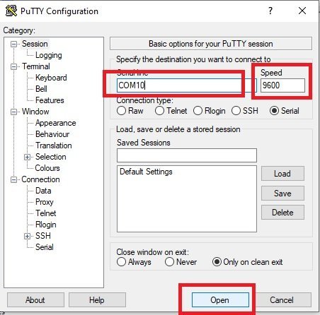
Now open PuTTY and configure it according to the figure below: Serial line = your COM port, Speed = 115200. Click Open.
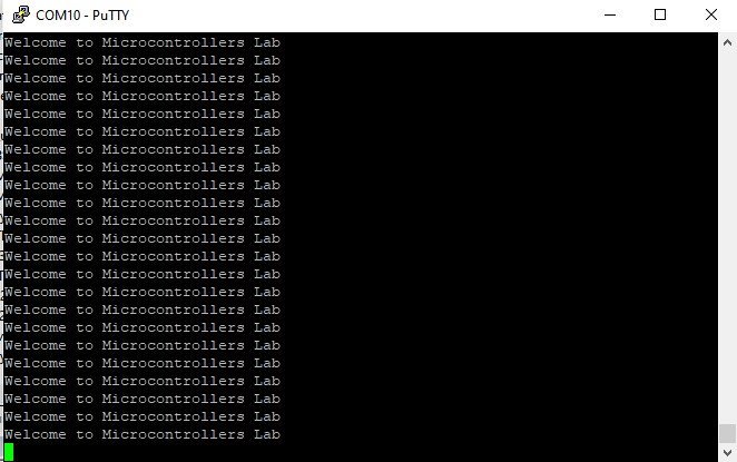
Press the reset button on the STM32F4 Discovery Board. You should see the welcome string stream into the serial console as shown in the figure below:
STM32F4 UART Receive Example
The next example extends the previous one: the STM32F4 Discovery Board receives 4 characters on the UART2 Rx pin (PA3) and then echoes them back on the Tx pin (PA2). Whatever you type into PuTTY appears back in PuTTY, confirming that both directions of the UART link work.
Complete STM32F4 UART Echo Code
#include "stm32f4xx_hal.h"
#include <string.h>

/*Function prototype for delay and UART2 configuration functions */
void UART2_Configuration(void);
void Delay_ms(volatile int time_ms);

UART_HandleTypeDef UART_Handler; /*Create UART_HandleTypeDef struct instance */
char Message[] = "Write anything on Serial Terminalrn"; /* Message to be transmitted through UART */

int main(void)
{
	HAL_Init(); /* HAL library initialization */
	UART2_Configuration(); /* Call UART2 initialization define below */
	HAL_UART_Transmit(&UART_Handler, (uint8_t *)Message, strlen(Message), 10);
	while(1)
	{
		 uint8_t buffer[4];
     HAL_UART_Receive(&UART_Handler, buffer, sizeof(buffer), HAL_MAX_DELAY);
     HAL_UART_Transmit(&UART_Handler, buffer, sizeof(buffer), HAL_MAX_DELAY);
	}
}

void UART2_Configuration(void)
{
	__HAL_RCC_GPIOA_CLK_ENABLE(); /* Enable clock to PORTA - UART2 pins PA2 and PA3 */
	__HAL_RCC_USART2_CLK_ENABLE(); /* Enable clock to UART2 module */

	GPIO_InitTypeDef UART2_GPIO_Handler; /*Create GPIO_InitTypeDef struct instance */
	UART2_GPIO_Handler.Pin = GPIO_PIN_2 | GPIO_PIN_3;
	UART2_GPIO_Handler.Mode = GPIO_MODE_AF_PP;
	UART2_GPIO_Handler.Pull = GPIO_PULLUP;
	UART2_GPIO_Handler.Speed = GPIO_SPEED_FREQ_VERY_HIGH;
	UART2_GPIO_Handler.Alternate = GPIO_AF7_USART2;
	HAL_GPIO_Init(GPIOA, &UART2_GPIO_Handler);
	//UART Configuration
	UART_Handler.Instance = USART2;
	UART_Handler.Init.BaudRate = 115200;
	UART_Handler.Init.Mode = UART_MODE_TX_RX;
	UART_Handler.Init.WordLength = UART_WORDLENGTH_8B;
	UART_Handler.Init.StopBits = UART_STOPBITS_1;
	UART_Handler.Init.OverSampling = UART_OVERSAMPLING_16;
	HAL_UART_Init(&UART_Handler);
}

void SysTick_Handler(void)
{
  HAL_IncTick();
  HAL_SYSTICK_IRQHandler();
}
/*Generate ms */
void Delay_ms(volatile int time_ms)
{
	      int j;
        for(j = 0; j < time_ms*4000; j++)
            {}  /* excute NOP for 1ms */
}
Receive Demo
Follow the same wiring steps as the transmit example. After flashing the code to the STM32F4 Discovery Board, open PuTTY and type any 4 characters. Whatever you type is sent from the PC over the FTDI cable to the STM32F4 Rx pin (PA3), the STM32F4 transmits it straight back on Tx (PA2), and PuTTY displays the echoed bytes.

Troubleshooting STM32F4 UART Issues
If nothing appears in your serial terminal, or the received characters look like garbled symbols, one of these issues is almost certainly the cause:
- Garbled / random characters in PuTTY. The baud rate in your terminal doesn’t match the baud rate in your firmware. The STM32F4 code above is 115200, so PuTTY must also be set to 115200. Mismatched baud rates always produce garbage — not silence.
- No output at all. Tx and Rx are swapped, or GND is not connected. Remember: STM32 Tx → FTDI Rx, STM32 Rx → FTDI Tx. Double-check the GND connection between the two boards.
- “Port not found” in PuTTY. Either the FTDI driver isn’t installed, or the COM number changed. Check Windows Device Manager under “Ports (COM & LPT)”.
- USART2 clock not enabled.
__HAL_RCC_USART2_CLK_ENABLE()must be called beforeHAL_UART_Init(). Without it, writes to the USART2 registers are silently ignored. - Alternate function not selected. PA2 and PA3 must be configured with
Mode = GPIO_MODE_AF_PPandAlternate = GPIO_AF7_USART2. Otherwise they behave as plain GPIO and the UART peripheral can’t reach the pins. - 5 V FTDI cable damaging the STM32. Many older FTDI cables are 5 V logic. Use a 3.3 V cable, or put level-shifters in between. A 5 V signal into a 3.3 V STM32F4 pin can destroy it over time.
- Floating pins when FTDI is disconnected. With the FTDI unplugged, the Rx pin floats and can pick up noise. The code above enables the internal pull-up (
GPIO_PULLUP) on PA2/PA3, which prevents this. - Data is missed at high baud rates. Polling mode is prone to missing bytes if the CPU is busy elsewhere. For reliable high-speed UART reception, switch to interrupt mode or DMA.
Frequently Asked Questions
How many UART/USART ports does the STM32F4 Discovery Board have?
The STM32F407VGT6 on the STM32F4 Discovery Board provides 4 USART channels (USART1, 2, 3, 6) and 2 UART channels (UART4, UART5) — six independent serial ports in total. The USART channels support both synchronous and asynchronous modes, while UART4 and UART5 are asynchronous only.
What is the difference between UART and USART on the STM32F4?
A USART (Universal Synchronous/Asynchronous Receiver-Transmitter) supports both asynchronous mode (standard UART) and synchronous mode, where a clock line is shared between the two devices. A UART (Universal Asynchronous Receiver-Transmitter) is asynchronous only. In most practical applications — PC terminals, Bluetooth modules, GPS — you use the asynchronous mode, so the distinction doesn’t usually matter.
What baud rates does the STM32F4 UART support?
The STM32F4 UART baud rate generator is a fractional divider driven by the APB peripheral clock. In theory it supports anything from a few baud up to fPCLK/8 (with oversampling by 8) — which at 84 MHz on APB2 means roughly 10.5 Mbit/s maximum. In practice you’ll use 9600, 19200, 38400, 57600, 115200, 230400, 460800, or 921600. 115200 is the most universal default.
Why do I need an FTDI or USB-to-serial cable?
The STM32F4’s UART produces 3.3 V logic-level serial signals, but your PC’s USB port speaks USB — a completely different protocol. A USB-to-serial adapter (FTDI FT232, CP2102, CH340G) is the bridge that converts between the two. Many STM32 Nucleo boards have this bridge built in over the ST-LINK’s virtual COM port, but the STM32F4 Discovery Board does not — which is why an external FTDI cable is required.
Can I use printf() with the STM32F4 UART?
Yes. Override the low-level _write() (or fputc(), depending on your toolchain) and route its output to HAL_UART_Transmit(). After that, any printf() call in your firmware sends formatted strings out over UART to your serial terminal. This is the standard technique used in almost every STM32 embedded debug setup.
How do I use UART in interrupt or DMA mode instead of polling?
The HAL library provides non-blocking equivalents — HAL_UART_Transmit_IT() and HAL_UART_Receive_IT() for interrupt mode, and HAL_UART_Transmit_DMA() and HAL_UART_Receive_DMA() for DMA. Both return immediately and fire a callback (HAL_UART_TxCpltCallback, HAL_UART_RxCpltCallback) when the transfer finishes. These modes are covered in the next tutorials in this STM32F4 series.
Conclusion
In this STM32F4 Discovery Board UART tutorial you learned how to use the UART/USART communication ports of the STM32F407VGT6 in polling mode using the HAL UART driver. You saw the STM32F4’s 6 USART/UART channels and their GPIO pin mappings, learned the APB1 vs APB2 clock distinction, walked through the UART_HandleTypeDef and UART_InitTypeDef structures, and built complete working examples that both transmit and receive characters over a real FTDI cable at 115200 baud. You now have the debugging and communication channel that virtually every embedded project needs. In the next tutorials we will extend this with interrupt-driven UART and DMA UART for high-throughput, low-overhead serial communication.