ATMega16 is one of the cheapest and most used microcontrollers due to its multiple pins and feature. It is closest to the ATmega328P but it is smaller in memory size and larger in pins. ATMEL designed ATMega16 by using RSIC CPU and 8-bit CMOS technology which helps it to operate with other TTL/CMOS devices by consuming less power. Its internal structure allows the designer to use the sleep mode, power vs performance methods to use it efficiently by consuming less power. The microcontroller comes in tow packaging and their pins vary at different packages.
Recommended Components
The following parts are used in this article, along with a generic electronics kit that is handy for building and testing the circuit.
| Component | How it’s used | Buy on Amazon |
|---|---|---|
| ATmega16 microcontroller | The ATmega16 8-bit AVR microcontroller this article covers. | Check Price |
| Electronic component assortment kit (1390 pcs) | A handy assortment of resistors, capacitors, LEDs, diodes and transistors for building circuits. | Check Price |
| Digital multimeter (AstroAI) | Measures voltage, current, resistance and checks continuity while you build and debug. | Check Price |
| Breadboard | Solderless base for prototyping the circuit. | Check Price |
| Jumper Wires | Make the connections on the breadboard. | Check Price |
As an Amazon Associate we earn from qualifying purchases. Prices and availability are accurate as of the date/time indicated and are subject to change.
Introduction to ATmega16 Microcontroller
The AVR ATmega16 is a low-power CMOS 8-bit microcontroller based on the AVR enhanced RISC architecture. The throughput of AVR ATmega16 is about 1 MIPS per MHz using a single clock per instruction allowing the system designer to optimize power consumption versus processing speed. The AVR has 32 general purpose working registers and a rich instruction set. They are directly connected to the ALU and allow two independent registers to be accessed in one single instruction executed in one clock cycle. Getting started with the Avr microcontroller tutorial helps you to understand real-time examples. Atmel Studio 6 is used for writing c code and generating hex file.
ATmega16 Microcontroller Pinout Diagram Details
This section consists of pin configuration details and step by step information on each GPIO pin.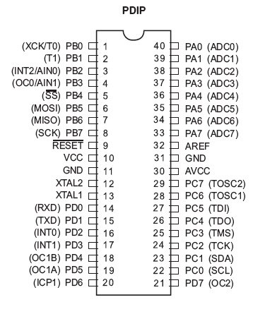 Power: Every microcontroller required power to operate and ATMega16 gives three power pins, one is power input and the remaining two are ground pins, those are internally connected with each other. Those pins in the microcontroller are:
- VCC – Pin10
- GND – Pin11, Pin31
- XTAL2 – GPIO12
- XTAL1 – GPIO13
- PA0 – GPIO40
- PA1 – GPIO39
- PA2 – GPIO38
- PA3 – GPIO37
- PA4 – GPIO36
- PA5 – GPIO35
- PA6 – GPIO34
- PA7 – GPIO33
- PB0 – GPIO1
- PB1 – GPIO2
- PB2 – GPIO3
- PB3 – GPIO4
- PB4 – GPIO5
- PB5 – GPIO6
- PB6 – GPIO7
- PB7 – GPIO8
- PC0 – GPIO22
- PC1 – GPIO23
- PC2 – GPIO24
- PC3 – GPIO25
- PC4 – GPIO26
- PC5 – GPIO27
- PC6 – GPIO28
- PC7 – GPIO29
- PD0 – GPIO14
- PD1 – GPIO15
- PD2 – GPIO16
- PD3 – GPIO17
- PD4 – GPIO18
- PD5 – GPIO19
- PD6 – GPIO20
- PD7 – GPIO21
- INT0 – GPIO16
- INT1 – GPIO17
- INT2 – GPIO3
- TX (output) – GPIO15
- RX (input) – GPIO14
- XCK (clock I/O) – GPIO1
- SS’ – GPIO5
- MOSI – GPIO6
- MISO – GPIO7
- SCK – GPIO8
- SDA – GPIO23
- SCL – GPIO22
- TDI (test data in) – GPIO27
- TDO (test data out) – GPIO26
- TMS (test mode selects) – GPIO25
- TCK (test clock) – GPIO24
- T0 – GPIO1
- T1 – GPIO2
- TOSC1 – GPIO28
- TOSC2 – GPIO29
- AN0 – GPIO3
- AN1 – GPIO4
- OC0 – GPIO4
- OC1A – GPIO19
- OC1B – GPIO18
- OC2 – GPIO21
- ICP – GPIO20
- AVCC – GPIO30
- ADC0 – GPIO33
- ADC1 – GPIO34
- ADC2 – GPIO35
- ADC3 – GPIO36
- ADC4 – GPIO37
- ADC5 – GPIO38
- ADC6 – GPIO39
- ADC7 – GPIO40
- AREF – GPIO32
- Reset – GPIO9
ATmega16 Microcontroller Features
The AVR ATmega16 provides the following features:
We used Atmega16 because of the following features:
- It has low power CMOS 8-bit controller with AVR RISC
- Its throughput is up to 16MIPS per
- It has 32 General purpose registers directly connected to
- 16 Kbytes In-System programmable flash
- 512 bytes of EEPROM, 1k byte SRAM, JTAG
- Three timer/counter for comparison
- Internal and external interrupts
- Serial programmable USART+I2C protocol
| FEATURES & SPECIFICATIONS | |
|---|---|
| CPU Architecture | 8-bit RISC Architecture |
| CPU Frequency | 16MHz |
| Operating Voltage Range | (4.5V – 5.5V) |
| GPIO PORTS | 32 I/O Pins |
| Interrupts | 3 |
| Timers | 3 (Two 8-bit and one 16-bit timer) |
| PWM | 4 CCP |
| ICP | One ICP Pin |
| USART | One USART channel |
| Serial Interface | One serial interface (two wired) |
| I2C | One I2C channel |
| SPI | One SPI channel |
| JTAG | Available |
| Self-Programming | Available |
| Watchdog timer | Available |
| LAN | Not Available |
| CAN | Not Available |
| ADC | 8 Channel |
| Enhanced USART Module | 1 Channel |
| SRAM | 1Kb |
| FLASH (Program Memory) | 16Kb |
| EEPROM | 512 bytes |
| Comparator | 1 |
| Packages | PDIP (40-Pins), TQFP (44-Pins) & MLF (44-Pins) |
ATmega16 Microcontroller GPIO Ports and Peripherals
Port A (PA7-PA0) It is used for analog inputs of A / D. But if A/D converter is not enabled it also serves as a self in 8-bit bi-directional port for input and output. Port pins can provide internal pull-up resistors (selected for each bit).
Port B (PB7-PB0) Port B is used as input/output 8-bit bi-directional port having internal pull- up resistors. The output buffers of Port B are of symmetrical drive characteristics having high sink and source capability. When acting as input pins, Port B pins; if pulled externally low; will source current if the pull-up resistors are activated.
Port C (PC7-PC0) Port C’s special feature is JTAG interface. If the JTAG interface is enabled, the pull-up resistors on pins PC5 (TDI), PC3 (TMS) and PC2 (TCK) will be activated even if a reset occurs. Along with this Port C can also be used as input/output 8-bit bi-directional port having internal pull-up resistors.
Port D (PD7-PD0) Port D serves the functions of various special features of the ATmega16 like interrupts input, timer/counter output and UART. In addition to this Port D is used as input/output 8-bit bi-directional port having internal pull-up resistors.
Microcontroller CLOCK SOURCES
ATmega16 has the following clock source options, selectable by Flash Fuse bits as shown below. The clock from the selected source is input to the AVR clock generator and routed to the appropriate modules. In device clocking option for External Crystal or Ceramic Resonator combination for bits is 1111 or 1010. For External Low-frequency Crystal it is 1001 and for External RC Oscillator 1000 or 0101. Calibrated Internal RC Oscillator 0100 or 0001 and for External Clock it is 0000. Bit “1” means un-programmed while “0” means programmed.
Microcontroller USART Module
Main feature used from microcontroller is USART used for serial communication between controller and GSM modem. The Universal Synchronous and Asynchronous serial Receiver and Transmitter (USART) is a highly supple serial communication device.General Baud rates supported are 1200, 1800, 2400, 4800, 7200, 9600, 14400, 19200, 38400,57600, 115200. In our project we are using 9600. Serial USART Hardware Elements include:
- USART Clock Generator to provide clock source and set baud rate using UBRR
- USART Transmitter to send a character through TxD pin and handle start/stop bit framing, parity bit, shift
- USART Receiver to receive a character through RxD pin and performs the reverse operation of the
- USART Registers to configure control and monitor the serial
USART Baud Rate Registers comprises of two registers, UBRRH and UBRRL, i.e. in total 16 bits. The UBRRH Register shares the same I/O location as the UCSRC Register. To cater this bit 15 (URSEL) i.e. Register Select is used. This bit selects between accessing the UBRRH or the UCSRC Register. It is read as zero when reading UBRRH. The URSEL must be zero when writing the UBRRH. Bit 14:12 are reserved bits for future use. For compatibility with future devices, these bits must be written to zero when UBRRH is written. Bits 11-0 contain the USART baud rate. The UBRRH contains the four most significant bits, and the UBRRL contains the 8 least significant bits of the USART baud rate. Ongoing transmissions by the transmitter and receiver will be corrupted if the baud rate is changed. Writing UBRRL will trigger an immediate update of the baud rate Prescaler.
USART Control & Status Registers comprises of three registers; UCSRA, UCSRB, and UCSRC; and hold flags and control bits for USART. UCSRA contains following flags: RXC (USART Receive Complete), TXC (USART Transmit Complete), UDRE (USART Data Register Empty), FE (Frame Error), DOR (Data OverRun), PE (Parity Error), MPCM (Multi-processor Communication Mode) and control bit U2X (Double the USART Transmission Speed). UCSRB contains following control bits: RXCIE (RX Complete Interrupt Enable), TXCIE (TX Complete Interrupt Enable), UDRIE (USART Data Register Empty Interrupt Enable), RXEN (Receiver Enable), TXEN (Transmitter Enable), UCSZ2 (Character Size), RXB8 (Receive Data Bit 8) and TXB8 (Transmit Data Bit 8). UCSRC contains following control bits: URSEL (Register Select), UPM1:0 (Parity Mode), USBS (Stop Bit Select), UCSZ1:0 (Character Size) and UCPOL (Clock Polarity).
USART Data Register is the buffer for characters sent or received through the serial port. To start sending a character, write it to UDR. Then to check a received character, read it from UDR. Serial USART main tasks are initializing the serial port, sending a character, receiving a character and sending/receiving formatted strings. Initializing serial port includes setting USART communication parameter (data bit, stop bit, and parity bit), enable transmitter and receiver, setting USART for asynchronous mode and set the baud rate. For sending a character UDRE flag has been set to 1 and then write the character to register UDR for transmission. For receiving a character RXC flag has been set to 1 and then read the received character from register UDR.
ATMega16 Block Diagram
The block diagram of the ATMega16 is given below: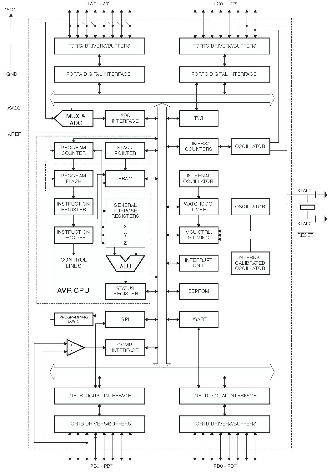
Applications
- The microcontroller found in commercial products.
- It is compatible with multi-sensor devices because most of the pins perform only a single operation.
- Smart industrial machines also use the ATMega16 due to its cheapness and functionality.
- To calculate the frequency and duty cycle of the external device, the ATMega16 is used.
2D Dimension diagram
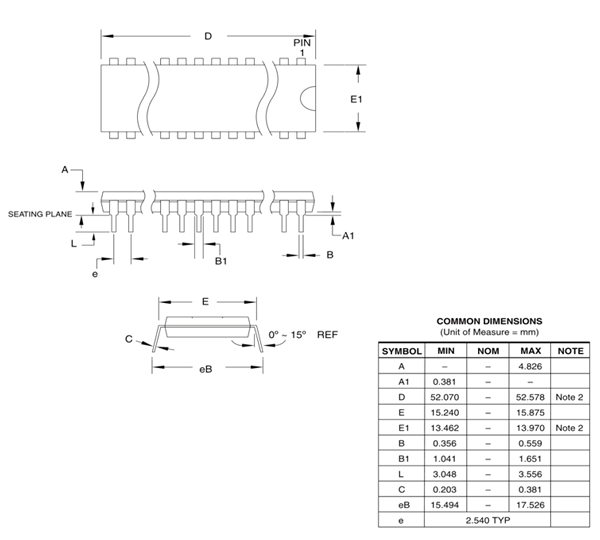
This is a 2D physical dimension diagram for the DIP package.