ATtiny45 is one of the most popular microcontrollers due to its small size and multiple features. This microcontroller available in multiple embedded systems and even you can find its applications at the industrial level. ATtiny45 microcontroller allows the designer to optimize power vs performance through programming. It is designed by using AVR and RSIC technology which makes it less power consumption controller and usage of its internal oscillator make it save more power. In short, most of the developing board and student project uses ATtiny85 to minimize the size of the project, also the size of the microcontroller can be reduced more by using its different packages. In this tutorial, we will see the following :
- Pin configuration diagram
- Pinout details
- Features and Peripherals
- Applications and datasheet
Recommended Components
The following parts are used in this article, along with a generic electronics kit that is handy for building and testing the circuit.
| Component | How it’s used | Buy on Amazon |
|---|---|---|
| ATtiny45 microcontroller | The ATtiny45 8-bit AVR microcontroller this article covers. | Check Price |
| Electronic component assortment kit (1390 pcs) | A handy assortment of resistors, capacitors, LEDs, diodes and transistors for building circuits. | Check Price |
| Digital multimeter (AstroAI) | Measures voltage, current, resistance and checks continuity while you build and debug. | Check Price |
| Breadboard | Solderless base for prototyping the circuit. | Check Price |
| Jumper Wires | Make the connections on the breadboard. | Check Price |
As an Amazon Associate we earn from qualifying purchases. Prices and availability are accurate as of the date/time indicated and are subject to change.
Pin Diagram ATtiny45
In this section, we will explain the pin configuration details. We will also go through all peripherals according to pinout details.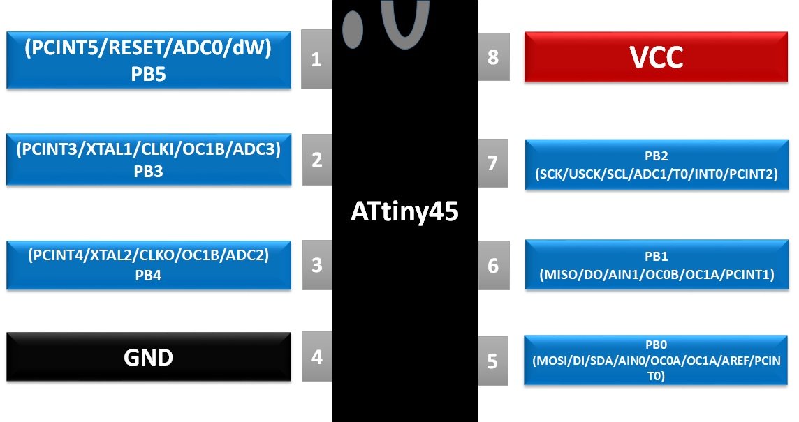
Pin Configuration Explanation Attiny45
Now we will begin to see pin diagram details and all peripherals attached to them. This information is according to the datasheet. It provides a summary of the lengthy datasheet.
POWER PINS
ATtiny45 has only two power pins due to its limited number of pins. One pin will be used as the power input and the second one will be used as a ground pin. The ground pin will be used to make the common ground with the microcontroller and external devices. Power pins in ATtiny45 are:
- VCC – Pin8
- GND – Pin4
OSCILLATOR/CLOCK PINS
The microcontroller comes with internal 0-8MHz but it also gives the ability to 10 to 20MHz. The value of the external clock depends on a different package. The external oscillator/clock required external pins which are:
- XTAL1/CLKI – GPIO2
- XTAL2/CLKO – GPIO3
TIMER Module Attiny45
ATtiny45 has two internal 8-bit timers which can be used for counting. The counting can be done with programming but a timer0 has an external input pin that can be used to receive the input pulse by which timer will count the value. Timer0 external pulse input pin is:
- T0 – GPIO7
DIGITAL INPUT/OUTPUT PINS
In this microcontroller, there is only one GPIO Port (Port B) which gives the ability to gives multiple I/O functions. Port B has input pull up resistors which allow the input function and port can also give the output signals which can be initialized through programming. I/O pins in the microcontroller are:
- PB0 – GPIO5
- PB1 – GPIO6
- PB2 – GPIO7
- PB3 – GPIO2
- PB4 – GPIO3
- PB5 – GPIO1
INTERRUPT PINS
Almost every circuit required an interrupt pin in case of an emergency code or to interface with some module requirement. ATtiny45 has a single interrupt pin which can be used to get the attention of CPU through programming. Interrupt pin on the microcontroller is given below:
- INT0 – GPIO7
ATtiny45 SPI (Three Wire) Communication
Most of the modules use a different kind of communications system and SPI is one of them. In ATtiny45 SPI protocol is used for programming by using a debug pin. Due to unavailability of “slave select” pin the controller can use its output pins to communicate with SPI communication devices:
- MOSI/DO – GPIO5
- MISO/DI – GPIO6
- SCK/USCK – GPIO7
I2C Communication Module
For a two-wire serial communication, I2C protocol can be used in the controller. This method required two wires, one for the clock pulse and one for data transmission/receiving. Both of these pins are listed below:
- SDA (data) – GPIO5
- SCL (clock) – GPIO7
dW Pin
There are multiple ways to program the microcontroller one of the ways is through SPI protocol. Some SPI devices can be used to program the controller but to program the controller a debug pin will be required. This pin comes in some specific controllers only. Debug pin on ATtiny45 is given below:
- dW – GPIO1
ANALOG COMPARATOR Module ATtiny45
It is used to compare the analog input signals. The analog comparator has input pins but it doesn’t provide any output pins. The comparator output can only be used by internal registers for further processing or it can be programmed to give the specific output on specific compared value. Input pins receive the same analog signal in inverted and non-inverted form. Analog comparator pins on the microcontroller are:
- AN0 – GPIO5
- AN1 – GPIO6
ATtiny45 Microcontroller CAPTURE/COMPARE/PWM
PWM generation is a required output signal for most of the devices to control their speed and capture/compare/PWM allows the microcontroller to generate the PWM with different clock pulse by using Prescaler. Capture keeps taking the input signal and keeps comparing with the timer0 and timer1 and then gives the output on according to the instructed program and it comes in a non-overlapped signal. The output pins on the microcontroller are:
- OC1B’ – GPIO2
- OC0B – GPIO6
- OC1B – GPIO3
- OC1A – GPIO6
- OC1A’ – GPIO5
- OC0A – GPIO5
ANALOG TO DIGITAL CONVERTER Channels
ATtiny45 has a 10-bit analog to digital converter which takes the input from four analog input channel and then it stores the data within a 10-bit register. The data can be used internally through a program or it can be received at the output pins. Analog to Digital Converting pins on ATtiny45 are:
- ADC0 – GPIO1
- ADC1 – GPIO7
- ADC2 – GPIO3
- ADC3 – GPIO2
AREF PINS
All ADC uses the power supply voltages as a reference to measure the analog signal value but in ATtiny45 there is an analog reference pin that can be used to convert the analog signal levels according to the voltages given on the analog reference pin. The analog reference pin is:
- AREF – GPIO5
RESET PINS
The Microcontroller comes with internal and external reset. The external reset pin on ATtiny45 can be used by external modules or buttons in case of a requirement to reset the controller. The external reset pin on ATtiny45 is:
- RESET – GPIO1
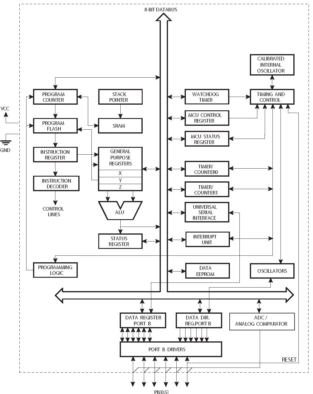
Block Diagram ATtiny45 Microcontroller
The block diagram of the microcontroller is given below. This diagram depicts all the peripherals available. It also provides a demonstration of the 8-bit data bus and address bus.
ATtiny45 Microcontroller Programming
To program Atmel microcontrollers, we always need a compiler. These are the popular compilers used for programming in c language or assembly language.- Atmel Studio ( Getting started guide on Avr studio)
- Mikro C for AVR
- AVR – GCC
- AVR – toolchain for Windows and Linux
Programming with Arduino ISP
Arduino Uno has ISP pins that we can use to program Attinyxx chips using Arduino IDE. Just make connections of any ATtinyxx series microcontroller with Arduino like this picture:
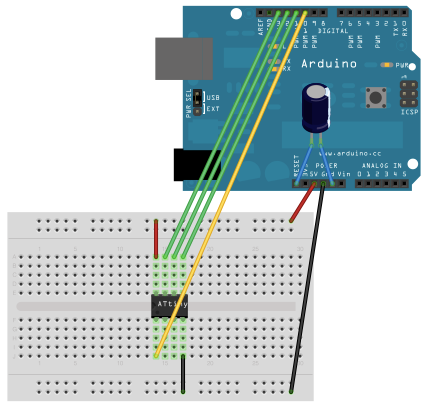
| Arduino Uno R3 Pins | ATtiny45 Chip Pins |
|---|---|
| 5 Volts Pin | Vcc Pin |
| Ground | Ground |
| Pin 13 | Pin 2 |
| Pin 12 | Pin 1 |
| Pin 11 | Pin 0 |
| Pin 10 | Reset |
- First of all, make hardware connection like the above circuit diagram and according to table
- Open an Arduino IDE and Select the required processor
- From Arduino IDE menue>>Programmer – Select Arduino as ISP
- You can change operating frequency of the processor also. To change frequency, go to tools>>Clock and select frequency
- Burn the bootloader to ATtiny45
- After that write a test program/code and upload to your device
PERIPHERALS
ATtiny45 also comes with different kinds of peripherals. All of them are available here.
SELF PROGRAMMING: It is one of the most popular and efficient programming methods within the controller. In self-programming, the data get stored in boot memory and then execute at the startup. Self-programming is efficient when it needs to execute the same program every time, which helps to solve the memory issue and increase controller efficiency.
USI: It is one of the best communication methods for every controller. It comes in two wires and three wires. In a microcontroller, the three-wire method is known as SPI and two-wire is known as I2C. Both of these methods transmit data serially and SPI method allows the microcontroller to program the instructions within microcontroller using SPI protocol.
DEAD TIME GENERATOR: In ATtiny45 dead time generator is used which is connected to the output pins. By using dead time generator microcontroller gets the ability to generate the output signal with a different pulse. The output signal also can be generated in non-overlap and overlap form by ATtiny45.
Applications Attiny45
- Display unit like LCD mostly come up with tiny microcontrollers.
- In an industrial unit to perform a single task ATiny45 is used.
- ATtiny45 is used in both commercial and development level due to its performance.
- Power Regulation system is operated able with ATtiny45.
2D DIAGRAM
