In this user guide, we will create an ESP32 and ESP8266 momentary switch web server that will be able to control the ESP32 and ESP8266 GPIO outputs using Arduino IDE. A momentary switch is just like a button you press and hold to get a specific action, but as soon as you release your finger, the button returns to its initial position. In other words, as long as the switch is being pressed, it will act as an on button. As soon as we release the button, the switch turns OFF. We will create a similar button to create on our web server.

This will act as a momentary switch. As long as we will press the button, the output will remain HIGH and it will go back to LOW state, once the switch is released. Inside our program code, we will configure the ESP32 and ESP8266 GPIO2 pins as an output. This is connected to the onboard LED. You can use any other output as well e.g., buzzers, relays, and different LEDs. Examples of momentary switch uses include doorbells, computer mouse buttons, and game controller buttons.
Prerequisites:
We will use Arduino IDE to program the ESP32 or ESP8266 NodeMCU development board. Therefore, you should have the latest version of Arduino IDE. Additionally, you also need to install the ESP32 and the ESP8266 add-on plugins in Arduino IDE. If your IDE does not have the plugins installed, you can visit the link below:
Installing ESP32 library in Arduino IDE and upload code
Installing ESP8266 library in Arduino IDE
Recommended Components
The following components are used in this project or are helpful for building it with the ESP32.
| Component | How it’s used in this project | Buy on Amazon |
|---|---|---|
| ESP32 Development Board (DevKit V1) | The main board that runs the project firmware. | Check Price |
| ESP8266 NodeMCU (ESP-12E) | An alternative Wi-Fi board; this tutorial works on the ESP8266 NodeMCU as well. | Check Price |
| Micro USB Cable | Connects the board to your computer to upload code and power it. | Check Price |
| Breadboard | Holds the board and components together while you wire up the project. | Check Price |
| Jumper Wires | Make the connections between the board and any external parts. | Check Price |
| 5mm LED | An external LED on a GPIO pin to visualise the controlled output. | Check Price |
| Tactile push button | A physical momentary switch to pair with the web-based momentary control. | Check Price |
As an Amazon Associate we earn from qualifying purchases. Prices and availability are accurate as of the date/time indicated and are subject to change.
ESP32 ESP8266 Momentary Switch Web Server Overview
We will create an asynchronous web server with a momentary switch. It will consist of a title, “ESP Momentary Switch Web Server,” and an output controlling button that will act as the switch. Our goal is to build a webpage through which the user will control the onboard LED of their ESP board through the momentary switch button. The button will act as a momentary switch.

When the user will enter the IP address in a web browser the web page will be sent to the client. Initially, the button will be in a LOW state.
When the user will press the button, the ESP board will receive an HTTP GET request on the /ON URL. The state of the button will turn HIGH and the on-board LED will turn ON. The LED will remain ON as long as the button is pressed.
Once the button is released, the ESP will receive an HTTP GET request on the /OFF URL. Thus, the state of the button goes back to LOW. This turns the onboard LED OFF.

Installing ESPAsyncWebServer Library and Async TCP/ ESP Async TCP Library
We will learn how to build an asynchronous image web server with the help of the ESPAsycWebServer library.
We will need two libraries to build our web server.
- ESP32: ESPAsyncWebServer & AsyncTCP
- ESP8266: ESPAsyncwebServer & ESPAsyncTCP
The ESPAsyncWebServer library will help us in creating our web server easily. With this library, we will set up an asynchronous HTTP server. AsyncTCP (for ESP32 only) and ESPAsyncTCP (for ESP8266 only) library will also be incorporated as it a dependency for the ESPAsyncWebServer library. All of these libraries are not available in the Arduino library manager. Therefore, we will have to download and load them on our ESP32/ESP8266 board ourselves.
For ESP32 & ESP8266
To install the ESPAsyncWebServer library for free, click here to download. You will download the library as a .zip folder which you will extract and rename as ‘ESPAsyncWebServer.’ Then, transfer this folder to the installation library folder in your Arduino IDE.
For ESP32 Only
To install the Async TCP library for free, click here to download. You will download the library as a .zip folder which you will extract and rename as ‘AsyncTCP.’ Then, transfer this folder to the installation library folder in your Arduino IDE.
For ESP8266 Only
To install the ESPAsync TCP library for free, click here to download. You will download the library as a .zip folder which you will extract and rename as ‘ESPAsyncTCP.’ Then, transfer this folder to the installation library folder in your Arduino IDE.
Likewise, you can also go to Sketch > Include Library > Add .zip Library inside the IDE to add the libraries as well. After installation of the libraries, restart your IDE.
ESP32 ESP8266 Momentary Switch Web Server Code
Open your Arduino IDE and go to File > New to open a new file. Copy the code given below in that file. This code will work for both ESP32 and ESP8266 development boards. You just need to enter your network credentials.
#ifdef ESP32
  #include <WiFi.h>
  #include <AsyncTCP.h>
#else
  #include <ESP8266WiFi.h>
  #include <ESPAsyncTCP.h>
#endif
#include <ESPAsyncWebServer.h>

// REPLACE WITH YOUR NETWORK CREDENTIALS
const char* ssid = "Your_SSID";
const char* password = "Your_Password";

const int led_output = 2;

// HTML web page
const char index_html[] PROGMEM = R"rawliteral(
<!DOCTYPE HTML><html>
  <head>
    <title>ESP Web Server</title>
    <meta name="viewport" content="width=device-width, initial-scale=1">
    <style>
      body { font-family: Times New Roman; text-align: center; margin:0px auto; padding-top: 30px;}
      .button {
        padding: 10px 20px;
        font-size: 24px;
        text-align: center;
        outline: none;
        color: #fff;
        background-color: #ff0522;
        border: none;
        border-radius: 5px;
        cursor: pointer;
        -webkit-touch-callout: none;
        -webkit-user-select: none;
        -khtml-user-select: none;
        -moz-user-select: none;
        -ms-user-select: none;
        user-select: none;
        -webkit-tap-highlight-color: rgba(0,0,0,0);
      }
      .button:hover {background-color: #ff0522 }
      .button:active {
        background-color: #1fe036;
        transform: translateY(2px);
      }
    </style>
  </head>
  <body>
    <h1>ESP Momentary Switch Web Server</h1>
    <button class="button" onmousedown="toggleCheckbox('ON');" ontouchstart="toggleCheckbox('ON');" onmouseup="toggleCheckbox('OFF');" ontouchend="toggleCheckbox('OFF');">Momentary Switch: Press to Turn ON</button>
   <script>
   function toggleCheckbox(x) {
     var xhr = new XMLHttpRequest();
     xhr.open("GET", "/" + x, true);
     xhr.send();
   }
  </script>
  </body>
</html>)rawliteral";


AsyncWebServer server(80);

void setup() {
  Serial.begin(115200);
  WiFi.mode(WIFI_STA);
  WiFi.begin(ssid, password);
  if (WiFi.waitForConnectResult() != WL_CONNECTED) {
    Serial.println("WiFi not connected");
    return;
  }
  Serial.println();
  Serial.print("IP Address: ");
  Serial.println(WiFi.localIP());

  pinMode(led_output, OUTPUT);
  digitalWrite(led_output, LOW);

  // Send web page to client
  server.on("/", HTTP_GET, [](AsyncWebServerRequest *request){
    request->send_P(200, "text/html", index_html);
  });

  // Receive an HTTP GET request
  server.on("/ON", HTTP_GET, [] (AsyncWebServerRequest *request) {
    digitalWrite(led_output, HIGH);
    request->send(200, "text/plain", "OK");
  });

  // Receive an HTTP GET request
  server.on("/OFF", HTTP_GET, [] (AsyncWebServerRequest *request) {
    digitalWrite(led_output, LOW);
    request->send(200, "text/plain", "OK");
  });


  server.begin();
}

void loop() {

}
How does the Code Work?
This code is compatible with both ESP32 and ESP8266 boards except for parts where we are defining the state of the LED. For ESP8266, the onboard LED works on an opposite logic as compared to ESP32. To turn the onboard LED ON, a low signal is sent, and to turn it OFF, a high signal is sent. This is the opposite in the case of ESP32.
Include Libraries
Firstly, we will include all the necessary libraries which are required for this project. As this code is compatible with both ESP32 and ESP8266 thus both libraries (WiFi.h and ESP8266WiFi.h) are defined. This library will help in establishing the connection between our ESP module to a wireless network. We will also import the two libraries which we installed previously, the ESPAsyncWebServer library and the ESPAsyncTCP library.
#ifdef ESP32
  #include <WiFi.h>
  #include <AsyncTCP.h>
#else
  #include <ESP8266WiFi.h>
  #include <ESPAsyncTCP.h>
#endif
#include <ESPAsyncWebServer.h>
Setting Network Credentials
Next, we will create two global variables, one for the SSID and the other for the password. These will hold our network credentials which will be used to connect to our wireless network. Replace both of them with your credentials to ensure a successful connection.
const char* ssid = "Your_SSID";
const char* password = "Your_Password";
Setting output GPIO
Then, we will define the variable led_output to save the GPIO pin through which the on-board LED is connected i.e., GPIO2.
const int led_output = 2;Creating the Web Page
We will create an index_html variable to store all the HTML, CSS, and Javascript text which will be required to build our web page. We will start with the title of the web page. The <title> tag will indicate the beginning of the title and </tile> tag will indicate the ending. In between these tags, we will specify “ESP Web Server” which will be displayed in the browser’s title bar.
<title>ESP Web Server</title>Next, we will create a meta tag to make sure our web server is available for all browsers e.g., smartphones, laptops, computers etc.
<meta name="viewport" content="width=device-width, initial-scale=1">CSS styling
Inside the index_html variable, we have the <style></style> tags which mark the beginning and end of the CSS styling file.
We will set the display text to font type Times New Roman and align it in the center of the webpage. For the heading and the button, the font size, font type, color, positioning, and everything relating to the overall visuals of the web page will be specified. We will distinguish the button through color.
Red color: Button in a LOW state. On-board LED OFF.
Green color: Button is in a HIGH state. On-board LED ON.
This section of code shows the CSS styling which we will incorporate in our web page.
<style>
      body { font-family: Times New Roman; text-align: center; margin:0px auto; padding-top: 30px;}
      .button {
        padding: 10px 20px;
        font-size: 24px;
        text-align: center;
        outline: none;
        color: #fff;
        background-color: #ff0522;
        border: none;
        border-radius: 5px;
        cursor: pointer;
        -webkit-touch-callout: none;
        -webkit-user-select: none;
        -khtml-user-select: none;
        -moz-user-select: none;
        -ms-user-select: none;
        user-select: none;
        -webkit-tap-highlight-color: rgba(0,0,0,0);
      }
      .button:hover {background-color: #ff0522 }
      .button:active {
        background-color: #1fe036;
        transform: translateY(2px);
      }
    </style>
HTML Body
  <body>
    <h1>ESP Momentary Switch Web Server</h1>
    <button class="button" onmousedown="toggleCheckbox('ON');" ontouchstart="toggleCheckbox('ON');" onmouseup="toggleCheckbox('OFF');" ontouchend="toggleCheckbox('OFF');">Momentary Switch: Press to Turn ON</button>
   <script>
   function toggleCheckbox(x) {
     var xhr = new XMLHttpRequest();
     xhr.open("GET", "/" + x, true);
     xhr.send();
   }
  </script>
  </body>
</html>)rawliteral";
The next step will be to define the HTML web page body. This will go inside the <body></body> tags which mark the beginning and the ending of the script. This part will include the heading of the web page and the button. We will include the heading of our webpage inside the <h1></h1> tags and it will be ‘ESP Momentary Switch Web Server’. You can use any other heading as you prefer.
<h1>ESP Momentary Switch Web Server</h1>Defining the Button
Now, we will create the momentary switch button. We will define the button inside <button></button> tags. We will provide the different attributes and the text as shown below:
<button class="button" onmousedown="toggleCheckbox('ON');" ontouchstart="toggleCheckbox('ON');" onmouseup="toggleCheckbox('OFF');" ontouchend="toggleCheckbox('OFF');">Momentary Switch: Press to Turn ON</button>On the button the following text will be displayed Momentary Switch: Press to Turn ON. Apart from that, we will include attributes as well.
Firstly, the class will contain the name of the momentary switch. In our case, we are naming it as a ‘button’. This will be used to refer to the switch when styling the web page.
Secondly, onmousedown is the attribute for the event. We will call the toggleCheckbox() function with ‘ON’ as an argument in case when the button is pressed. This is the JavaScript function which we will talk about later. Through this function, the HTTP GET request will be made to the ESP32/ESP8266 board regarding the output state to be turned HIGH.
Thirdly, onmousestart will also call the same function with the same argument toggleCheclbox(‘ON’). This will be useful for devices which have a touch screen. functionality.
Fourthly, onmouseup will call the toggleCheckbox() function but the argument passed inside is ‘OFF’. This will be called whenever the button will be released. The function will make a GET request to the ESP module to change the state to LOW.
Lastly, the ontouchend will be used for devices which have a touch screen. This will work similarly to onmouseup.
toggleCheckbox() function
function toggleCheckbox(x) {
  var xhr = new XMLHttpRequest();
  xhr.open("GET", "/" + x, true);
  xhr.send();
}
Next, we will define the toggleCheckbox() function. This is the JavaScript function which we were calling above when defining the attributes of the momentary switch button. Through this function, the HTTP GET request will be made to the ESP module regarding turning the LED on or off. It will create the HTTP GET request whenever a button will be pressed or released. This will be done by redirecting it on the /ON or /OFF URL.
Inside this function, we use the XMLHttpRequest. This will allow us to make an HTTP request in JavaScript. To make the HTTP GET request to we will follow three steps:
Firstly, we will create an XMLHttpRequest as follows:
var xhr = new XMLHttpRequest();Secondly, we will initialize the request by using the xhr.open() method. Inside it we will pass on three arguments. The first argument specifies the type of HTTP method which is GET in our case. The second argument is the URL to which are ESP32/ESP8266 will request upon. In our case, it will be either /ON or /OFF URL depending on the state of the button. The last argument is true which specifies that the request is asynchronous.
xhr.open("GET", "/" + x, true);Lastly, we will use xhr.send() to open the connection. Our server (ESP32/ESP8266) will now be able to receive the HTTP GET request whenever the user will interact with the button.
xhr.send();Creating the AsyncWebServer Object
The AsyncWebServer object will be used to set up the ESP web server. We will pass the default HTTP port which is 80, as the input to the constructor. This will be the port where the server will listen to the requests.
AsyncWebServer server(80);Setup() Function
Inside the setup() function, we will open a serial connection at a baud rate of 115200.
Serial.begin(115200);The following section of code will connect our ESP32/ESP8266 board with the local network whose network credentials we already specified above. After the connection will be established, the IP address of the ESP board will get printed on the serial monitor. This will help us to make a request to the server.
WiFi.mode(WIFI_STA);
  WiFi.begin(ssid, password);
  if (WiFi.waitForConnectResult() != WL_CONNECTED) {
    Serial.println("WiFi not connected");
    return;
  }
  Serial.println();
  Serial.print("IP Address: ");
  Serial.println(WiFi.localIP());
By using the pinMode() function, the led_output (GPIO2) will be passed as a parameter inside the function which will be configured as the output pin. We will initialize the pin to a LOW state at the time of boot that means the on-board LED will be OFF.
pinMode(led_output, OUTPUT);
digitalWrite(led_output, LOW);
ESP32/ESP8266 Handling Requests
In this section, we will discuss how our ESP board will handle the requests on the different URLs.
/root URL
server.on("/", HTTP_GET, [](AsyncWebServerRequest *request){
    request->send_P(200, "text/html", index_html);
  });
Firstly, we will deal with the /root URL request which the ESP board will receive.
We will use the send_P() method. This method will take in three parameters. The first is 200 which is the HTTP status code for ‘ok’. The second is “text/html” which will correspond to the content type of the response. The third input is the text saved on the index_httml variable which will be sent.
/ON URL
server.on("/ON", HTTP_GET, [] (AsyncWebServerRequest *request) {
    digitalWrite(led_output, HIGH);
    request->send(200, "text/plain", "OK");
  });
We will use the on() method on the server object to listen to the incoming HTTP requests and execute functions accordingly. The output state of GPIO2 will be set to HIGH through the digitalWrite() function.
The send() method will be used to return the HTTP response. It takes in three parameters. The first parameter is the response code which we will specify as 200. It is the HTTP response code for ok. The second parameter is the content type of the response which we will specify as “text/plain” and the third parameter is the actual message which we will be sent as the HTTP response. This is set as “OK”. The arrow operator will be used to call the send method on the AsyncWebServerRequest object.
/OFF URL
server.on("/OFF", HTTP_GET, [] (AsyncWebServerRequest *request) {
    digitalWrite(led_output, LOW);
    request->send(200, "text/plain", "OK");
  });
Then we will deal with the request received on the /OFF URL. Similarly, the output state of GPIO2 will be set to LOW through the digitalWrite() function:
This response will be returned through the send() method in the same way as it was for the /ON URL.
To start the server, we will call begin() on our server object.
server.begin();Demonstration
Make sure you choose the correct board and COM port before uploading your code to the board. Go to Tools > Board and select ESP32 Dev Module or ESP8266 Module.

Next, go to Tools > Port and select the appropriate port through which your board is connected.

Click on the upload button to upload the code into the ESP32/ESP8266 development board.
After you have uploaded your code to the development board, press its ENABLE/RESET button.


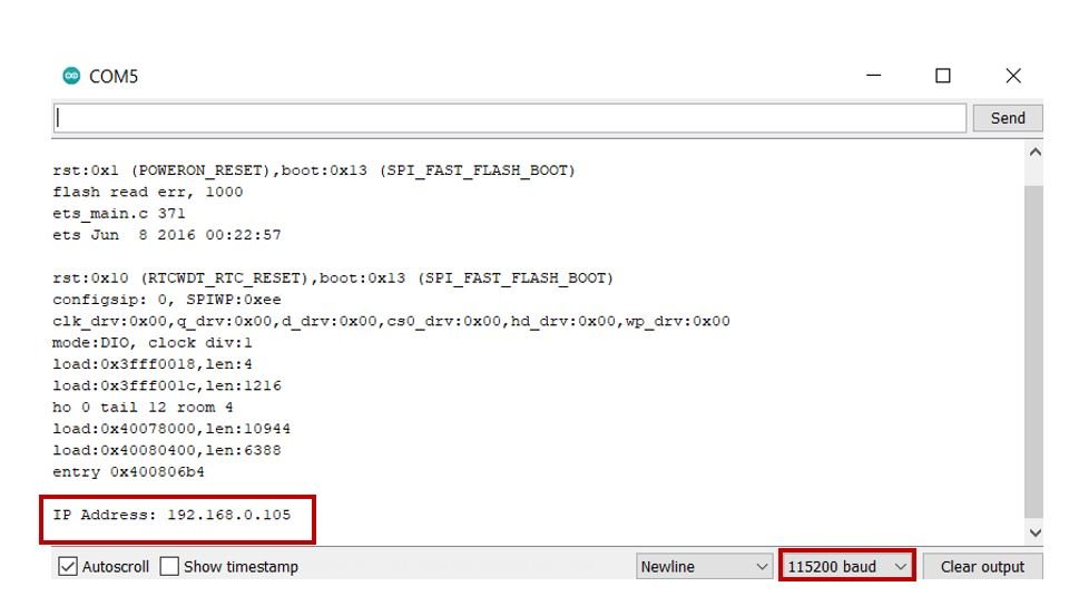
In your Arduino IDE, open up the serial monitor and you will be able to see the IP address of your ESP module.
Type that IP address in a web browser and press enter.
Now, press the button for a couple of seconds. Simultaneously the onboard LED will light up. When you will release the button, the LED will turn OFF.
Here is a short video of the demo below:
Conclusion
In conclusion, we have learned how to build an asynchronous web server capable of controlling ESP32/ESP8266 outputs via a momentary switch. For simplicity, we utilized GPIO2, connected to the onboard LED, but the program code provided can be adapted to control other GPIOs with ease.
More web server projects with ESP32 and ESP8266:
- Telegram ESP32 and ESP8266: Control GPIOs and LEDs using Arduino IDE
- Getting Current Date and Time with ESP8266 NodeMCU using NTP Server
- Displaying Images in ESP32 and ESP8266 Web Server
- ESP32/ESP8266 Web Server to Control Outputs with a Timer (Pulse Width)
- ESP8266 NodeMCU WebSocket Server using Arduino IDE
- ESP32 WebSocket Server using Arduino IDE
- ESP8266 NodeMCU Asynchronous Web Server using Arduino IDE
- ESP32/ESP8266 HTTP Authentication Web Server
- ESP32 Asynchronous Web Server using Arduino IDE
Well done!
How must the code looks like, if I want to have 16 pushbuttons to control 16 GPIO’s?
Thank you in advance!
Frank
How must the code looks like, if I want to have 2 pushbuttons to control 2 GPIO’s?
Did you find out i am wanting to know the same thing?
Is it possible a JavaScrip “if” inside (const char index_HTML) using a analog read from a sensor?