In this tutorial, we will build an IoT based soil moisture monitoring system with ESP32 and Adafruit IO. Firstly, we will show you how to interface soil moisture sensor e.g. HL-01 with ESP32. Not only that but we will build a soil moisture monitor that will indicate the percentage of moisture in soil on the Arduino serial monitor and an OLED display. Moreover, we will integrate Adafruit IO with our project and plot the soil moisture percentage to the software’s dashboard via MQTT protocol. Thus, we will also be able to monitor the readings in a line chart anywhere and anytime.

Adafruit IO is a highly interactive tool whereby the user can manage their project over the internet. From controlling LEDs, relays, electric motors to obtaining sensor data, Adafruit IO makes your project very accessible. For the user, it becomes extremely interactive and easy to use this application to control any ESP32 GPIO from anywhere over the internet.
Soil Moisture Sensor HL-01Introduction
The soil moisture sensor is also known as a hygrometer. It is used to measure the humidity level of moisture or it is used to measure the moisture content in the soil. You can also use it to measure water levels by using multiple moisture sensors.
A picture of the soil moisture sensor is shown below. It consists of two parts one is an electronic circuit on the right side of the picture which is used to adjust the sensitivity and the other on the left-hand side consists of two probes which we place in soil.

The sensor can measure the levels of moisture in the soil so it can be extremely useful if you want to monitor the soil moisture of your plants or automate the watering procedure. The two large exposed pads function as probes for the sensor. The more water in the soil the better the conductivity between the pads that results in a lower resistance. We get more voltage at the analog output since the resistance between the probes gets higher. We can set a threshold in order to enable the digital output at a certain moisture level using this potentiometer given with the electronics part of the sensor. In this tutorial, we will use the analog pin (A0) of the sensor module.
IoT based Soil Moisture Monitoring System Circuit Diagram
In this section, we will see how to connect a soil moisture sensor and an OLED module with ESP32. Firstly, let’s discuss ESP32 connections with the SSD1306 OLED display.
The OLED display has 4 terminals which we will connect with the ESP32 board. As the OLED display requires an operating voltage in the range of 3.3-5V hence we will connect the VCC terminal with 3.3V which will be in common with the ESP32 board. SCL of the display will be connected with the SCL pin of the module and the SDA of the display will be connected with the SDA of the module. By default, the I2C pin in ESP32 for SDA is GPIO21, and for SCL is GPIO22.
You can read this in-depth guide on OLED display interfacing with ESP32:
OLED Display Interfacing with ESP32 – Display Text, Draw shapes and Images
Similarly, a soil moisture sensor module also has 4 terminals but we will connect 3 of these with the ESP32 board as we are only using analog output. The VCC pin of the soil moisture sensor will be connected with the 3.3V pin of the ESP32 board. The A0 pin of the sensor will be connected with VP (GPIO36) of the ESP32 board. All three devices will be commonly grounded.
We will require the following components for this project.
Required Components:
- ESP32 development board
- Soil moisture sensor (HL-01)
- Connecting wires
- SSD1206 0.96 inch OLED display
- Breadboard
The diagram below shows the schematic diagram of ESP32 with an OLED display and soil moisture sensor.

As you can see we have connected the A0 pin of the sensor with GPIO36. The VCC and GND pins of the sensor are common between the ESP32 board and the OLED display. The rest of the OLED pins are interfaced with the ESP32’s I2C pins.
Getting Adafruit IO ready
Firstly, type https://io.adafruit.com/ in your browser search tab and press enter. This will open the main page. You will have to log in by creating an account. Click ‘Get Started for Free’ as highlighted in the red rectangular box.

- Now type all the relevant information and click ‘Create Account.’

- After you signed in with your account a new window will open. It will consist of the dashboard as shown below. Click ‘Feeds’

- Then go to ‘view all’

- Now, click ‘+ New Feed’

- Specify the name of your feed and description if you want to add that. Click, ‘Create’ to proceed.

- Your feed will be created. Next, go to Dashboards > view all > + New Dashboard

- Specify the name of your dashboard and description if you want to add on. Then click ‘Create’. You can use any name according to your preference.

- Click on the newly made dashboard. It will open up a window as shown below. Click the settings icon as highlighted in red below. Then go to, ‘+ Create New Block’.

- The following window will open. We want a line graph in our project so we will click on the ‘line chart’ block.

- Now select the feed which you created and move to the next step.

Specify the Chart settings. You can label the x and y-axis and also set a limit to the number of readings. Click ‘Create block’ to proceed.
Your dashboard will look something like this:

Accessing secret AIO key
Click ‘My Key’

Now you will be able to view your Adafruit IO key. Keep it safe with yourselves. We will need it while programming our ESP32 module in Arduino IDE. For safety concerns, do not share the key with anyone.

Installing Arduino Libraries for Soil Moisture Monitoring System
We will use Arduino IDE to program our ESP32 development board. Thus, you should have the latest version of Arduino IDE. Additionally, you also need to install the ESP32 plugin. If your IDE does not have the plugin installed you can visit the link below:
Installing ESP32 library in Arduino IDE and upload code.
Installing OLED Display Libraries
To use the OLED display in our project, we have to install the Adafruit SSD 1306 library and Adafruit GFX library in Arduino IDE. Follow the steps below to successfully install them.
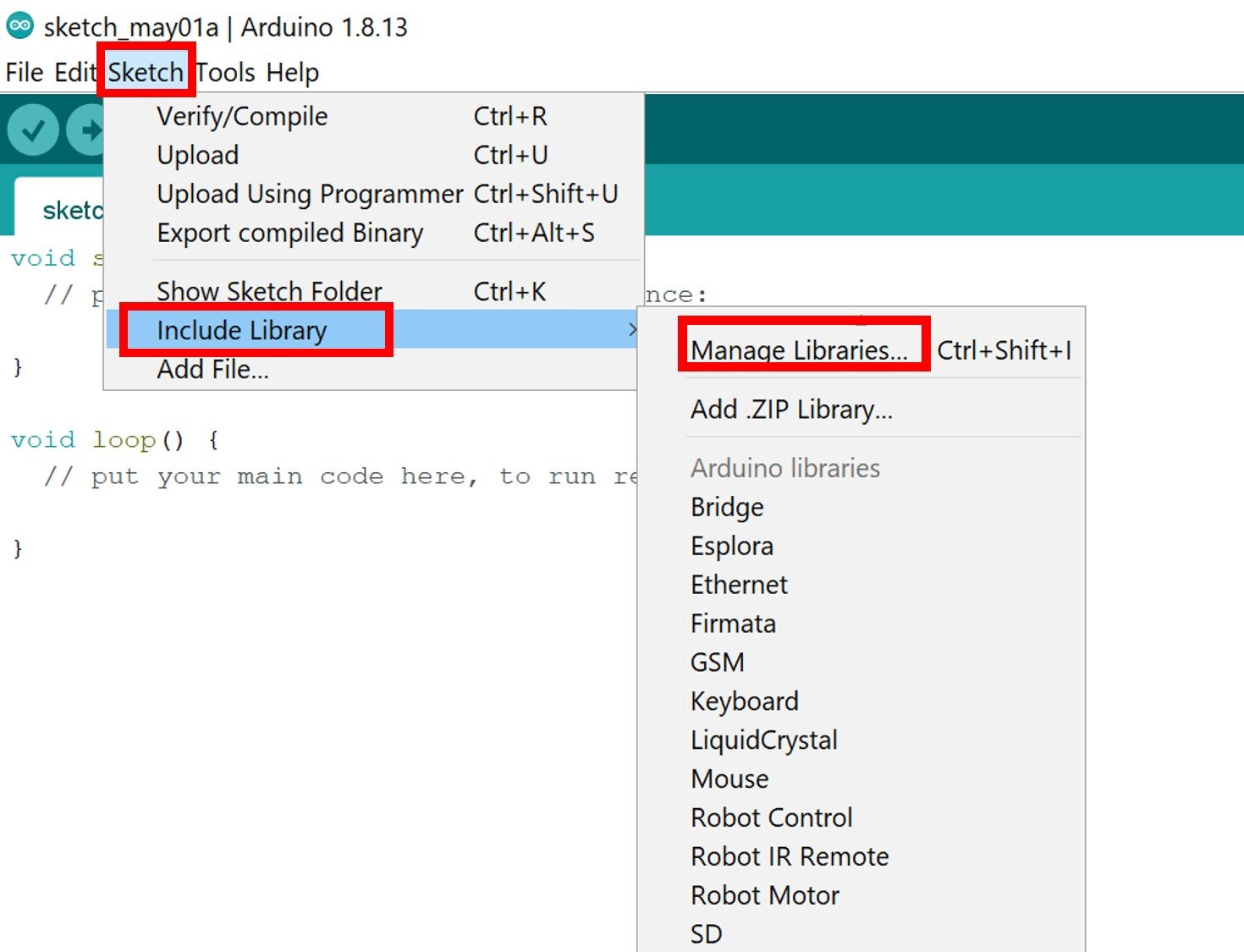
Open Arduino IDE and click on Sketch > Library > Manage Libraries
The following window will open up.

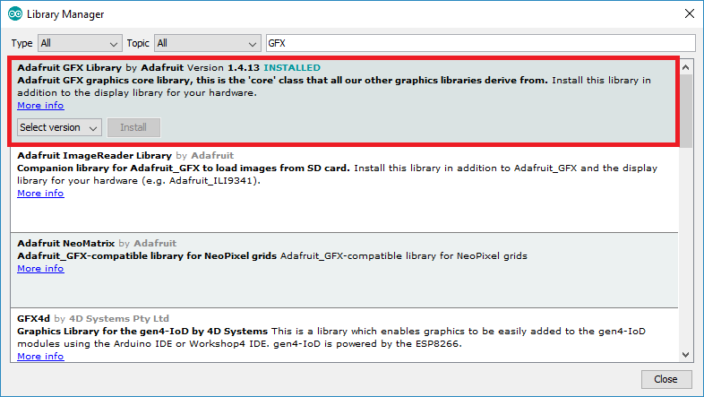
Type ‘SSD1306’ in the search tab and install the Adafruit SSD1306 OLED library.

We will also require the Adafruit GFX library which is a dependency for SSD1306. Type ‘Adafruit GFX’ in the search tab and install it as well.
Installing Adafruit MQTT Library
To use Adafruit IO with our ESP32 board we will require a library. We will install the Adafruit MQTT library from the Library Manager in our Arduino IDE. Open your Arduino IDE. Go to Sketch > Include Library > Manage Libraries. Type ‘Adafruit MQTT’ in the search bar and press enter. Install the latest version of the library.

After installation of the libraries, restart your IDE.
ESP32 Soil Moisture Monitoring System Arduino Sketch
Open your Arduino IDE and go to File > New to open a new file. Copy the code given below in that file. You need to enter your network credentials. Additionally, you also have to provide your Adafruit IO key and Adafruit username.
#include <WiFi.h>
#include <Wire.h>
#include <Adafruit_GFX.h>
#include <Adafruit_SSD1306.h>
#include "Adafruit_MQTT.h"
#include "Adafruit_MQTT_Client.h"

const char *ssid =  "Your_SSID";     // Enter your WiFi Name
const char *pass =  "Your_Password"; // Enter your WiFi Password

#define SCREEN_WIDTH 128
#define SCREEN_HEIGHT 64

Adafruit_SSD1306 display(SCREEN_WIDTH, SCREEN_HEIGHT, &Wire, -1);

WiFiClient client;

#define MQTT_SERV "io.adafruit.com"
#define MQTT_PORT 1883
#define MQTT_NAME "YOUR_USERNAME" // Your Adafruit IO Username
#define MQTT_PASS "aio_SuHF991XhtPfBnosM5ABahyi6***" //  Your Adafruit IO AIO key

const int Sensor_pin = 36;
int Sensor_value;

Adafruit_MQTT_Client mqtt(&client, MQTT_SERV, MQTT_PORT, MQTT_NAME, MQTT_PASS);
Adafruit_MQTT_Publish Sensor_data = Adafruit_MQTT_Publish(&mqtt, MQTT_NAME "/f/ESP32_Soil_Moisture_Monitor");

void setup()
{
  Serial.begin(115200);
  delay(10);
  WiFi.begin(ssid, pass);
  while (WiFi.status() != WL_CONNECTED)
  {
    delay(500);
    Serial.print(".");
  }
  Serial.println("");
  Serial.println("WiFi connected");

display.begin(SSD1306_SWITCHCAPVCC, 0x3C);
}
 void loop()
{
    MQTT_connect();
  Sensor_value = ( 100 - ( (analogRead(Sensor_pin) / 1023.00) * 100 ) );

  Serial.print("Soil Moisture is  = ");
  Serial.print(Sensor_value);
  Serial.println("%");

  display.clearDisplay();
  display.setTextSize(2);
  display.setTextColor(WHITE);
  display.setCursor(0, 10);
  display.println("Soil");
  display.setCursor(0, 30);
  display.println("Moisture");
  display.setCursor(0, 50);
  display.println(Sensor_value);
  display.setCursor(40, 50);
  display.println("%");
  display.display();

       if (! Sensor_data.publish(Sensor_value))
       {
         delay(5000);
          }
 delay(6000);
}

void MQTT_connect() {

  int8_t again;

  if (mqtt.connected()) {

    return;

  }

 Serial.print("Connecting to Adafruit IO");

uint8_t retry = 5;

  while ((again = mqtt.connect()) != 0) {

       Serial.println(mqtt.connectErrorString(again));

       Serial.println("Retrying Adafruit connection in 5 seconds...");

       mqtt.disconnect();

       delay(5000);

       retry--;

       if (retry == 0) {

         while (1);

       }

  }
  Serial.println("");

  Serial.println("Adafruit IO is Connected!");

}
How the Code Works?
Including Libraries
Firstly, we will include the necessary libraries required for this project. WiFi.h will help in establishing the connection between the ESP32 module to a wireless network. The Wire.h will allow us to communicate through the I2C protocol. Whereas the other libraries are the ones which we previously installed and are required for the proper functionality of the OLED display and the Adafruit MQTT protocol. We will include the Adafruit MQTT library to successfully connect our board with it.
#include <WiFi.h>
#include <Wire.h>
#include <Adafruit_GFX.h>
#include <Adafruit_SSD1306.h>
#include "Adafruit_MQTT.h"
#include "Adafruit_MQTT_Client.h"
Defining Network credentials
Next, we will define the network credentials. One for the SSID and the other for the password. These will be our network credentials which will be used to connect to our wireless network. Replace both of them with your credentials to ensure a successful connection.
const char *ssid =  "Your_SSID";     // Enter your WiFi Name
const char *pass =  "Your_Pasword"; // Enter your WiFi Password
Defining OLED Display
We will first define the width and height of our OLED display in pixels. We are using a 128×64 display hence the width will be 128 and the height will be 64.
#define SCREEN_WIDTH 128
#define SCREEN_HEIGHT 64
Next, we will initialize the display by creating an object of Adafruit_SSD1306 and specifying the width, height, I2C instance (&Wire), and -1 as parameters inside it.’ -1′ specifies that the OLED display which we are using does not have a RESET pin. If you are using the RESET pin then specify the GPIO through which you are connecting it with your development board.
Adafruit_SSD1306 display(SCREEN_WIDTH, SCREEN_HEIGHT, &Wire, -1);Defining Adafruit IO Credentials
Thirdly, we will specify the server name and port for Adafruit IO. You do not need to change these values. We will also define the Adafruit username through which we signed into our account and the IO key which we previously saved. Keep this key safe with you for security concerns. You will have to replace these two with your own credentials.
#define MQTT_SERV "io.adafruit.com"
#define MQTT_PORT 1883
#define MQTT_NAME "YOUR_USERNAME" // Your Adafruit IO Username
#define MQTT_PASS "aio_SuHF991XhtPfBnosM5ABahyi6***" //  Your Adafruit IO AIO key
Defining Sensor Pin
Then, we will define the variable called ‘Sensor_pin’. It will save the GPIO pin through which the A0 pin of the sensor is connected. In our case, it is GPIO36 that is the VP pin of the ESP32 board.
const int Sensor_pin = 36; Connecting with Adafruit IO
Next, we will create a WiFiClient and the Adafruit MQTT client. The Adafruit MQTT client will be set up with the WiFiClient, the Adafruit server name, and its port value. These will be configured as global variables so we can access them throughout our program code.
WiFiClient client;
Adafruit_MQTT_Client mqtt(&client, MQTT_SERV, MQTT_PORT, MQTT_NAME, MQTT_PASS);
Then create an instance of the feed which we created for our project named ‘ESP32_Soil_Moisture_Monitor’. We will pass the MQTT object and the path for our feed with the Adafruit username.
Adafruit_MQTT_Publish Sensor_data = Adafruit_MQTT_Publish(&mqtt, MQTT_NAME "/f/ESP32_Soil_Moisture_Monitor");setup()
Inside the setup() function, we will open a serial connection at a baud rate of 115200.
Serial.begin(115200);The following section of code will connect our ESP32 board with the local network whose network credentials we already specified above. We will use the WiFi.begin() function. The arguments will be the SSID and the password which we defined earlier in the code. After a successful connection is made, the serial monitor will display “WiFi connected”.
 WiFi.begin(ssid, pass);
  while (WiFi.status() != WL_CONNECTED)
  {
    delay(500);
    Serial.print(".");
  }
  Serial.println("");
  Serial.println("WiFi connected");
We will also initialize the OLED display by using display.begin(). Make sure you specify the correct address of your display. In our case, it is 0X3C.
display.begin(SSD1306_SWITCHCAPVCC, 0x3C);
loop()
In the infinite loop we will call the MQTT_connect() function and then use if statement to check if our readings are getting published to our feed or not.
Call the MQTT_connect() function to connect with your feed. In the void MQTT_connect() function we will try to connect our ESP32 with the MQTT server. This can be seen in the following definition of the function.
 void MQTT_connect() {

  int8_t again;

  if (mqtt.connected()) {

    return;

  }

 Serial.print("Connecting to Adafruit IO");

uint8_t retry = 5;

  while ((again = mqtt.connect()) != 0) {

       Serial.println(mqtt.connectErrorString(again));

       Serial.println("Retrying Adafruit connection in 5 seconds...");

       mqtt.disconnect();

       delay(5000);

       retry--;

       if (retry == 0) {

         while (1);

       }

  }
  Serial.println("");

  Serial.println("Adafruit IO is Connected!");

}
Then the sensor data from the soil moisture sensor gets saved in the variable ‘Sensor_value’ that is converted to a percentage.
Sensor_value = ( 100 - ( (analogRead(Sensor_pin) / 1023.00) * 100 ) );These percentages then get displayed on the serial monitor.
Serial.print("Soil Moisture is  = ");
Serial.print(Sensor_value);
Serial.println("%");
Moreover, we will display the soil moisture percentage on the OLED display as well. This is done by the following lines of code.
First, we will clear the buffer by using clearDisplay() on the Adafruit_SSD1306 object. Next, we will control the color of the text by using the setTextColor() function and passing WHITE as an argument. We will set the size of the text using setTextSize() and pass the size as a parameter inside it. Next, We have set the font size as 2. We will use the setCursor() function to denote the x and the y axis position from where the text should start. Then by using print() we will pass the text which we want to display on the OLED. We will set the cursor again at different positions to display all the strings properly. We will call the display() function on the display object so that the text displays on the OLED.
display.clearDisplay();
  display.setTextSize(2);
  display.setTextColor(WHITE);
  display.setCursor(0, 10);
  display.println("Soil");
  display.setCursor(0, 30);
  display.println("Moisture");
  display.setCursor(0, 50);
  display.println(Sensor_value);
  display.setCursor(40, 50);
  display.println("%");
  display.display();
This sensor data also gets published to our feed and is depicted in the form of a line chart.
 if (! Sensor_data.publish(Sensor_value))
       {
         delay(5000);
          }
Demonstration
Set up the ESP32 with the OLED display and the soil moisture sensor as we showed in the schematic diagram. For demonstration purposes, we will use a cup filled with soil and some water. Immerse the sensor probe in the cup.

Now it is time to upload code to ESP32 board. Choose the correct board and COM port before uploading your code to the board. Go to Tools > Board and select ESP32 Dev Module.

Next, go to Tools > Port and select the appropriate port through which your board is connected.

Click on the upload button to upload the code to your ESP32 development board.
After you have uploaded your code to the development board, press its ENABLE button.

Open your serial monitor and set the baud rate to 115200. You will be able to see the status of your WIFI and Adafruit connection. The soil moisture percentage readings will also start printing on the serial monitor.

The OLED display will also start displaying the soil moisture percentage as seen below:

Now to your Adafruit IO dashboard. You will be able to view the line chart as well.

Conclusion
In conclusion, we have learned how to use a soil moisture sensor with ESP32 development board using Arduino IDE. We displayed the soil moisture percentage on the OLED as well as published the sensor data to Adafruit IO feed via MQTT protocol. Through this technique, we were able to access and monitor the moisture percentage from anywhere over the internet.
For related articles, go through the links given below:
Excelente Tutorial, vou experimentar!
C:\Users\Hrushikesh\Documents\Arduino\mini project\mini project.ino:2:22: fatal error: Wire.h: No such file or directory
compilation terminated.
exit status 1
Compilation error: Wire.h: No such file or directory
con you veriy this