In this user guide, we will control the output of the ESP32 using Google Assistant and Adafruit IO. In the era of smart homes and interconnected devices, the integration of Internet of Things (IoT) technologies has paved the way for seamless control and monitoring of everyday objects. In this digital landscape, the ESP32 microcontroller has emerged as a powerful tool for building IoT applications due to its versatility and capabilities. This article shows how to use ESP32 microcontroller, Google Assistant, and Adafruit IO platform. By following the step-by-step guide outlined in this tutorial, you will learn how to harness the potential of these technologies to control ESP32 outputs using voice commands through Google Assistant and achieve real-time data visualization via Adafruit IO.
Previously, we controlled the ESP module’s outputs through applications such as Telegram, Google Firebase, and Blynk applications.
You can read the tutorials by going to the links below.
- Telegram ESP32 and ESP8266: Control GPIOs and LEDs using Arduino IDE
- Google Firebase: Control ESP32 Outputs with Arduino IDE
- Control ESP32 Outputs using Blynk App and Arduino IDE
This article is divided into these sub-topics:
- Introduction to Adafruit IO
- Getting Adafruit IO ready and using IFTTT to configure a trigger
- Connecting Google Assistant through IFTTT
- Setting up Arduino IDE to control LED using ESP32 and Google Assistant
Recommended Components
The following components are used in this project or are helpful for building it with the ESP32.
| Component | How it’s used in this project | Buy on Amazon |
|---|---|---|
| ESP32 Development Board (DevKit V1) | The main controller running the Adafruit IO MQTT client to receive voice commands from Google Assistant. | Check Price |
| Micro USB Cable | Connects the ESP32 to your computer to upload the sketch and power the board. | Check Price |
| Breadboard | Holds the ESP32 and any external output components while you prototype the project. | Check Price |
| Jumper Wires | Wire the ESP32 GPIO pins to an external LED or relay you want to control by voice. | Check Price |
| 5mm LED | An external LED you can drive from a GPIO pin to test the ON/OFF voice commands. | Check Price |
As an Amazon Associate we earn from qualifying purchases. Prices and availability are accurate as of the date/time indicated and are subject to change.
Adafruit IO Introduction
This time, we will show you another interesting application where we will be able to control any output connected to the ESP32’s GPIO pins through voice commands. We will use Adafruit IO, which is free cloud-based software built around the MQTT protocol. It is a highly interactive tool whereby the user can manage their project over the Internet. From controlling LEDs, relays, and electric motors to obtaining sensor data, Adafruit IO makes your project very accessible. For the user, it becomes extremely interactive and easy to use this application to control any AC appliance from anywhere over the internet.
Some key features of Adafruit IO
- Makes your project internet-connected.
- Connects your project to various web services
- Demonstrates your data online in real-time through a visually pleasing dashboard. The user can display charts, graphs, and display data e.g., sensor readings.
- Uses triggers that can control or react to the user’s data. Triggers can be configured according to the user’s preference. Some examples include sending sensor readings to personal email after a set amount of time or displaying messages as a response to a temperature/pressure sensor. The sensors could be connected with different web services through the integration of Adafruit IO with IFTTT or Zapier.
- Free and beginner-friendly
For this article, we will keep it simple and control the onboard LED of our ESP32 module through Google Assistant and Adafruit IO in Arduino IDE. We will use IFTTT to access the Google Assistant which will control the onboard LED through voice commands. After that controlling any other ESP32 module’s output with your voice will be relatively easy to follow.
Getting Adafruit IO ready
Firstly, type https://io.adafruit.com/ in your browser search tab and press enter. This will open the main page. You will have to log in by creating an account. Click ‘Get Started for Free’ as highlighted in the red rectangular box.

- Now type all the relevant information and click ‘Create Account.’

- After you signed in with your account a new window will open. It will consist of the dashboard as shown below. Click ‘Feeds’

- Then go to ‘view all’

- Now, click ‘+ New Feed’

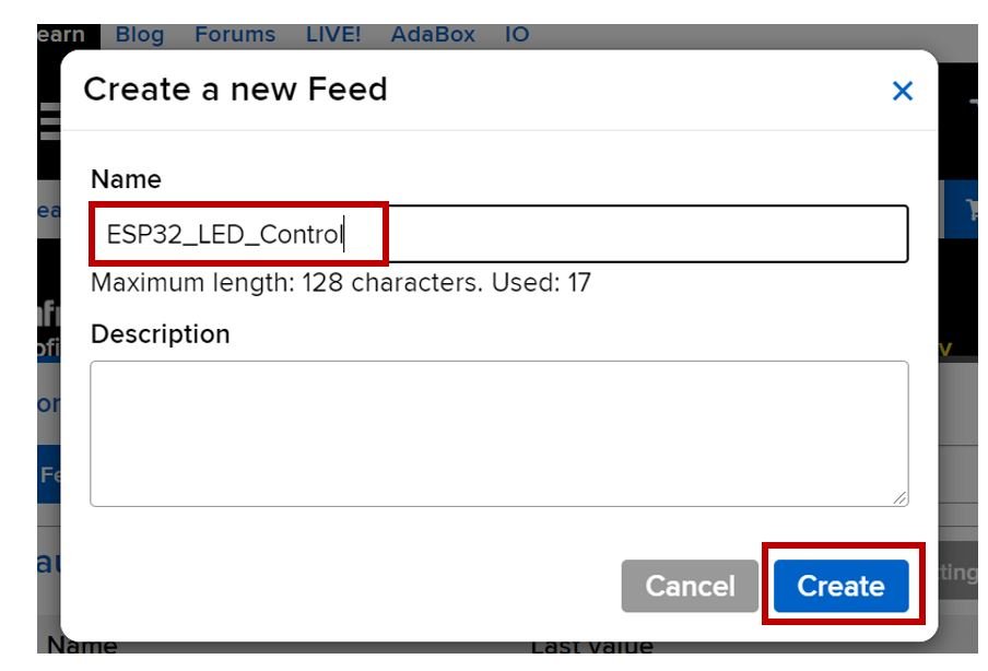
- Specify the name of your feed and description if you want to add that. Click, ‘Create’ to proceed.
- Your feed will be created. Next, go to Dashboards > view all > + New Dashboard

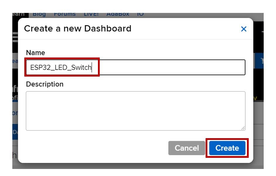
- Specify the name of your dashboard and description if you want to add on. Then click ‘Create’. You can use any name according to your preference.
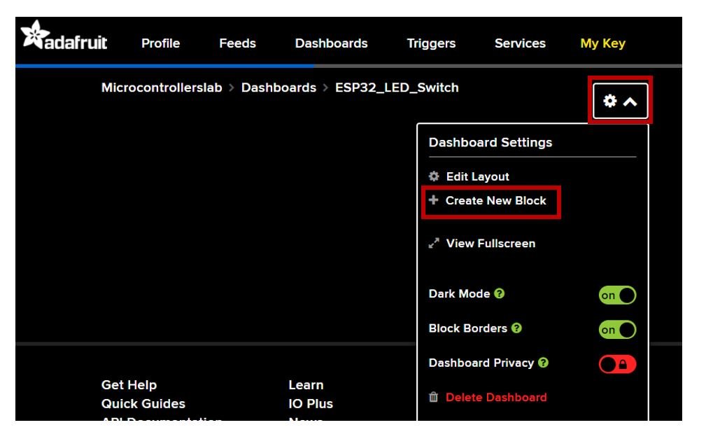
- Click on the newly made dashboard. It will open up a window as shown below. Click the settings icon as highlighted in red below. Then go to, ‘+ Create New Block’.
- The following window will open. We want a toggle button in our project so we will click on the ‘toggle’ block.

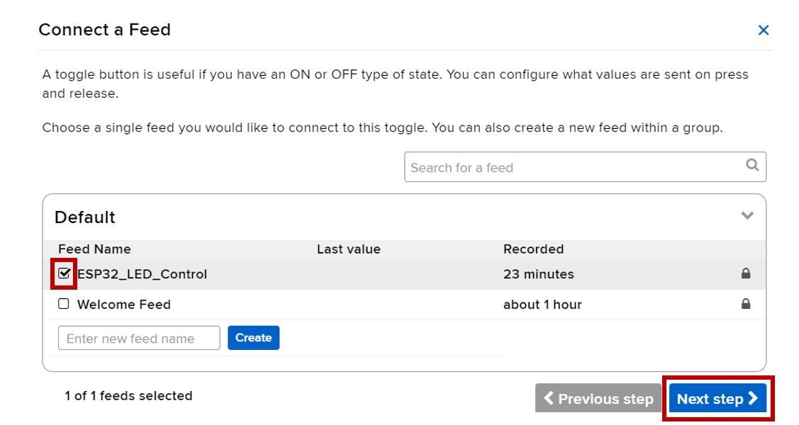
- Now select the feed which you created and move to the next step.
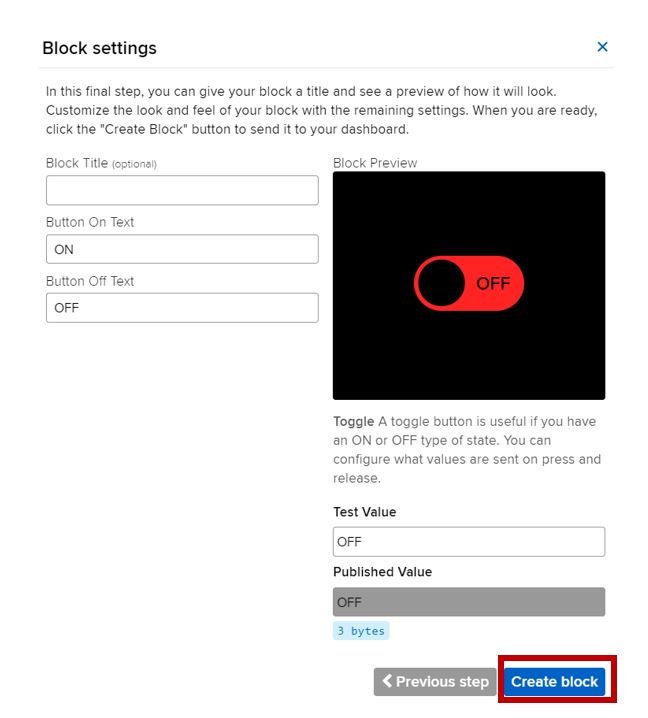
Specify the Button settings. We are using the default settings. Click ‘Create block’ to proceed.
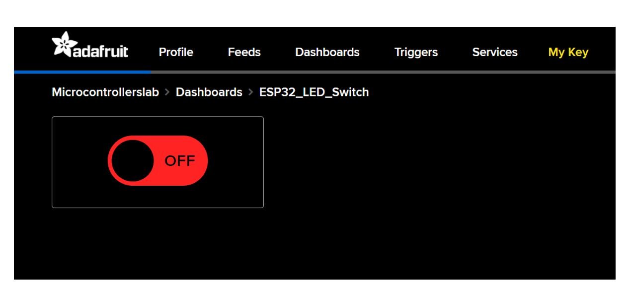
Your dashboard will look something like this:
Accessing secret AIO key
Click ‘My Key’
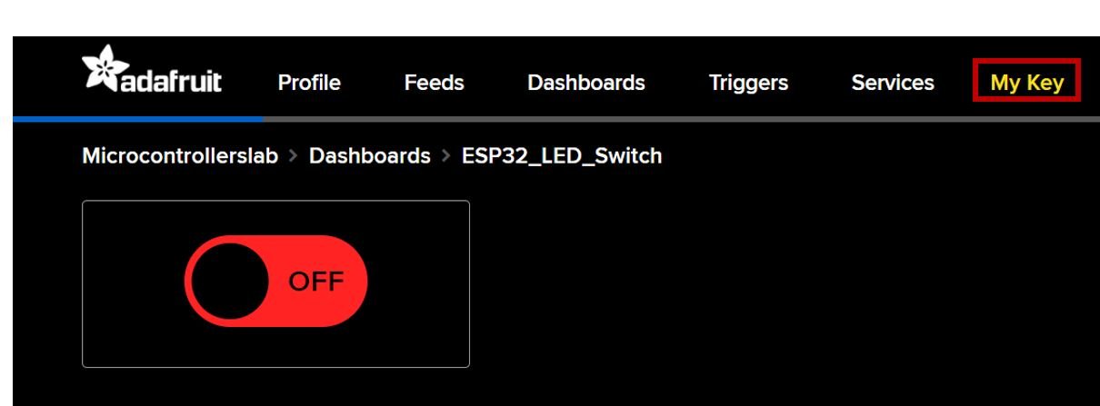
Now you will be able to view your Adafruit IO key. Keep it safe with yourselves. We will need it while programming our ESP32 module in Arduino IDE. For safety concerns, do not share the key with anyone.

Connecting to Google Assistant through IFTTT
Recommended readings:
- ESP32 HTTP POST using Arduino IDE (ThingSpeak and IFTTT)
- MicroPython: Send Sensor Readings via Email (IFTTT) with ESP32 and ESP8266
In this project, our goal is to control the onboard LED of ESP32 through voice commands. Thus, after setting up our Adafruit IO dashboard, the next step is to integrate Google Assistant into Adafruit IO. This will allow us to toggle the LED with our voice.
As we mentioned previously, Adafruit IO allows the user to set triggers for a particular action and its response. We will use the IFTTT service to configure the trigger for our project.
IFTTT means ‘If this, then that.’ It is an open-source service that gives the user the freedom to program a response to an event according to their likes. We can create an applet which are chains of conditional statements by a combination of several app services and add triggering parameters. For our project, we will be using this service, whenever the user will say a particular phrase then that data will be sent to Adadruit IO. To work with this web service, we will have to follow a series of steps to ensure the proper functionality.
Creating an IFFT Account
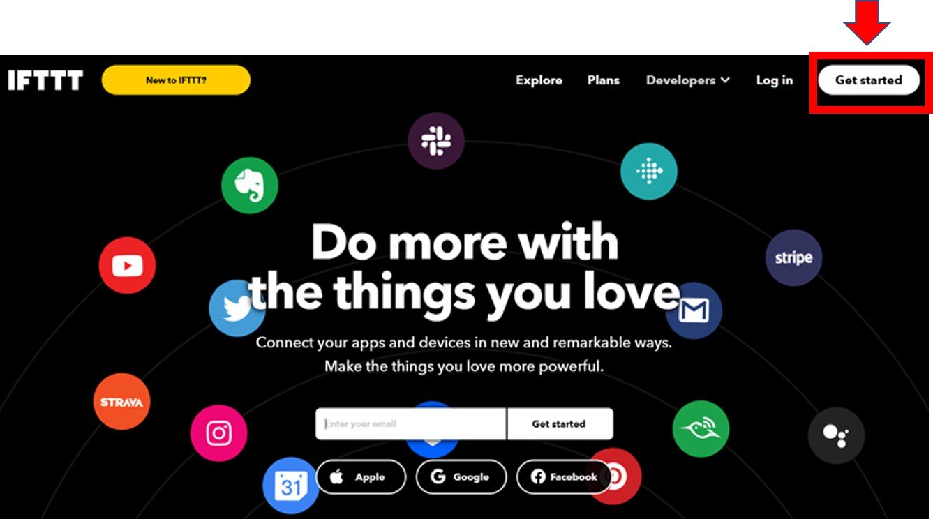
Although the IFTTT service is free to use, we will have to create an account. First go to the following website: https://ifttt.com/
The following window will appear. Click on the ‘Get Started’ button.
The following window will appear. You can select any one from these three options (Apple, Google, or Facebook) to connect. Or you can simply ‘sign up’ with your own given email. We will be following this scheme.
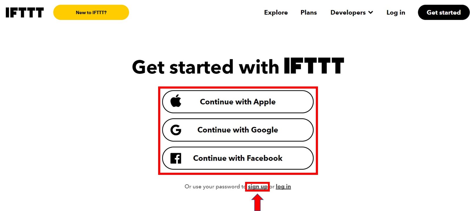
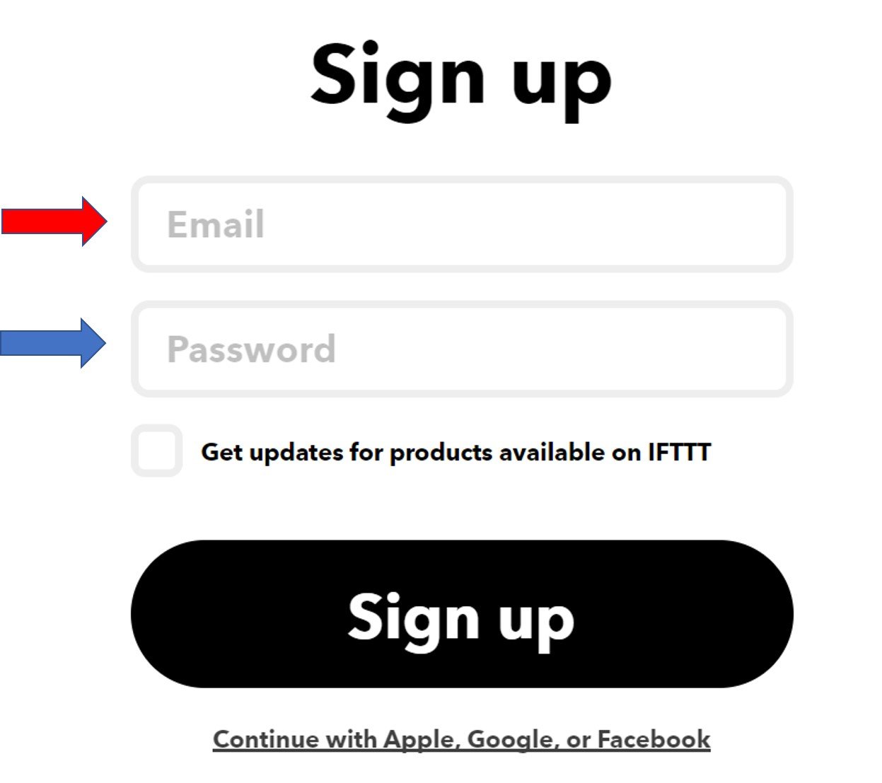
Click the ‘sign up’ tag. You will see the following window pop up. Enter your email address and password to start working in IFTTT. This whole process is free of cost for the first three applets.
Creating an Applet
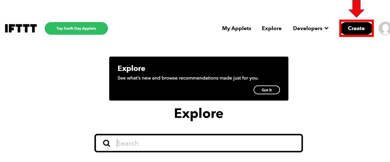
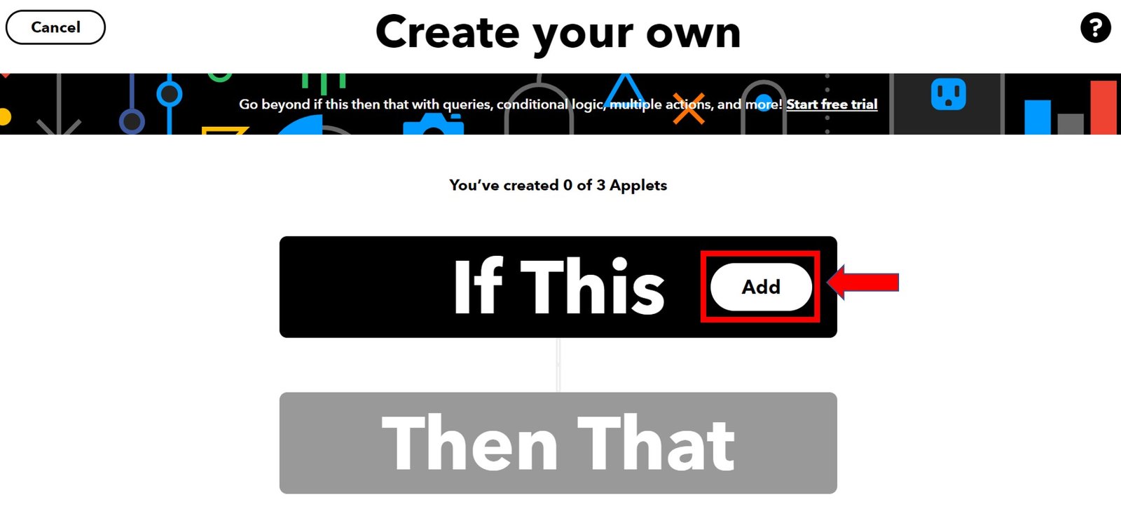
After you have created your account, we will be directed to the page where we will create our applet. Click on ‘Create.’
The following window opens up. Click the following Add button in the ‘If This’ section.
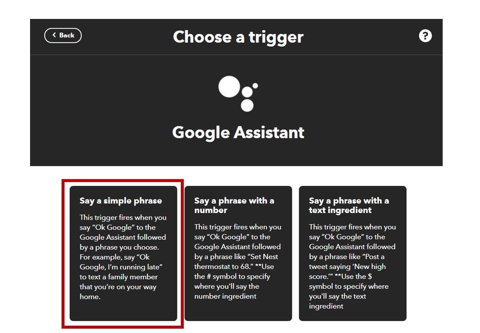
Another page will open in which we will have to choose our service. There is a lot of options to choose from. Write down ‘Google Assistant’ in the search option and its icon will appear:

Set Trigger:
Click the icon and choose your trigger. We will use ‘Say a simple phrase’ as our trigger.
Next, click the ‘Connect’ button to establish the connection.

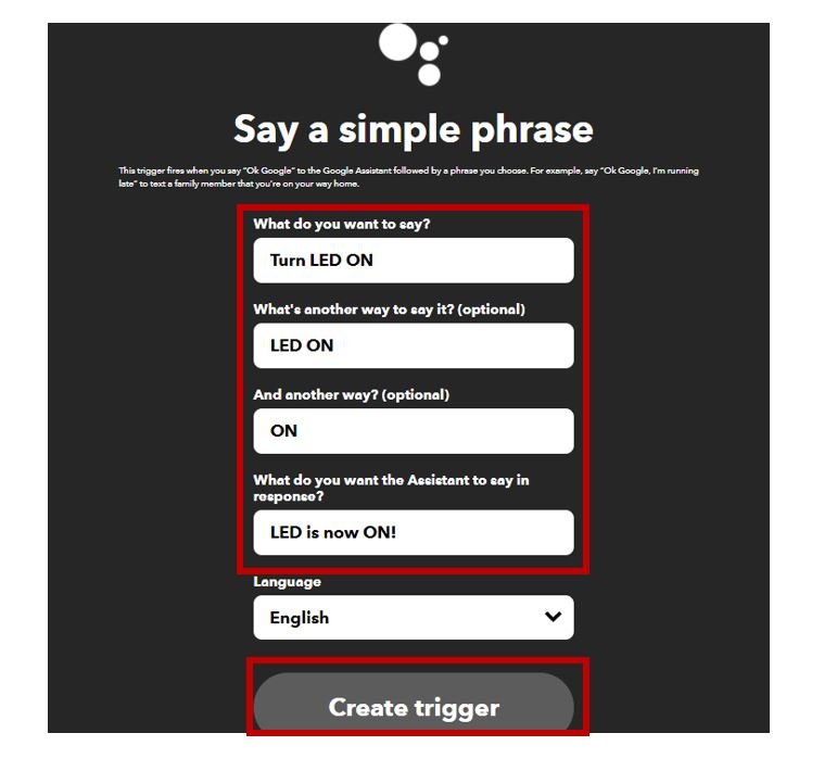
A new window will open which will let you sign in with your Google account. It will take permission for the voice commands as well. Now, we will specify the commands. You can add any text according to your preference.
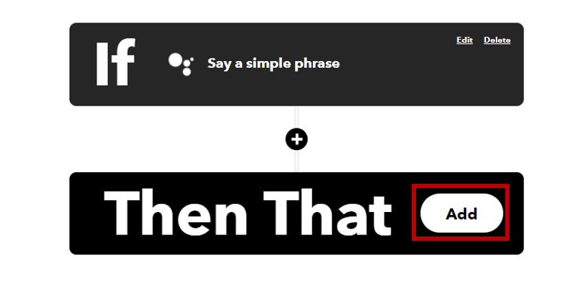
After the trigger is created, we are taken back to the web page where we first added the service for the ‘IF THIS’ section. Now we will click the ADD button for the ‘THEN THAT’ section.
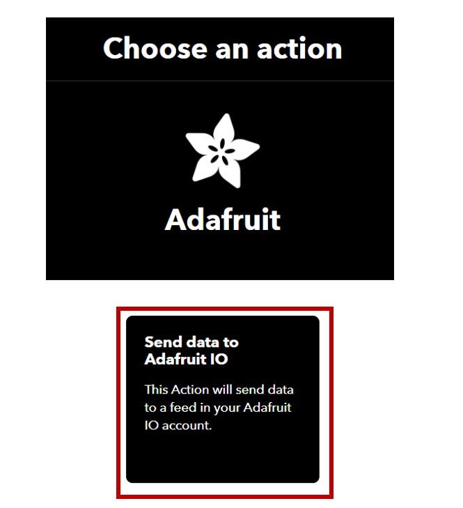
Now we will choose the service. We have to choose what will happen if a voice command is received. Thus, we will type ‘Adafruit’ in the search option and click on its icon.

Next, we will select the action. Click ‘Send data to Adafruit IO’.
Click the ‘Connect’ button.
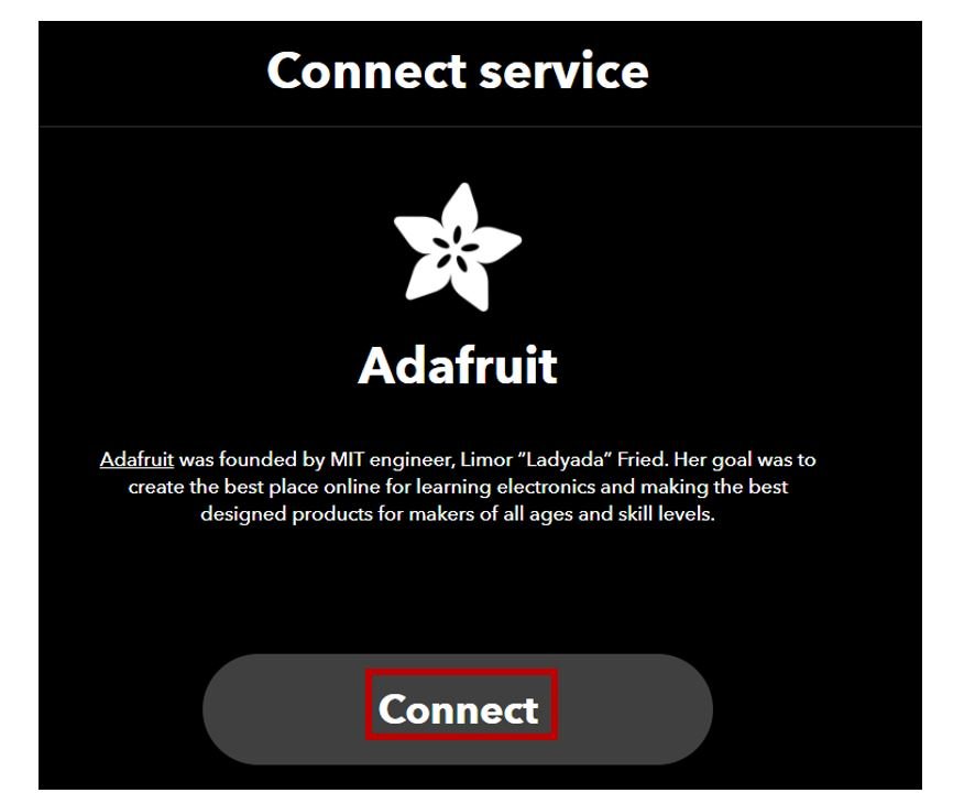
A new web page will open which will ask for your permission. Click ‘Authorize’.

Now specify the feed which you created and the data which will get saved. Click ‘Create action’.
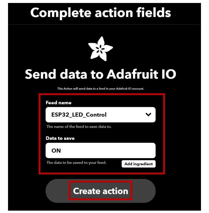
Click ‘Continue’ to proceed.

The applet title is shown. You can also turn on the notifications when it runs. Click ‘Finish’ to complete the process for the ‘Turn LED ON’ voice command.
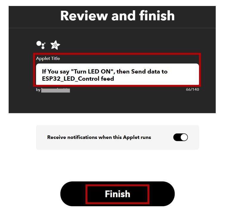
Similarly, we will create another applet for ‘Turn LED OFF’ voice command as well. In the end, we will have two applets running.

Setting up Arduino IDE
We will use Arduino IDE to program our ESP32 development board. Thus, you should have the latest version of Arduino IDE. Additionally, you also need to install the ESP32 plugin. If your IDE does not have the plugin installed you can visit the link below:
Installing ESP32 library in Arduino IDE and uploading code
Installing Adafruit MQTT Library
To use Adafruit IO with our ESP32 board we will require a library. We will install the Adafruit MQTT library from the Library Manager in our Arduino IDE. Open your Arduino IDE. Go to Sketch > Include Library > Manage Libraries. Type ‘Adafruit MQTT’ in the search bar and press enter. Install the latest version of the library.

ESP32 Code
Open your Arduino IDE and go to File > New to open a new file. Copy the code given below in that file. You need to enter your network credentials. Additionally, you also have to provide your Adafruit IO key and Adafruit username.
#include <WiFi.h>

#include "Adafruit_MQTT.h"

#include "Adafruit_MQTT_Client.h"

#define SSID       "Write_Your_SSID"

#define Password      "Write_your_Password"

#define AIO_SERVER      "io.adafruit.com"

#define AIO_SERVERPORT  1883

#define AIO_USERNAME    "Write_your_username"

#define AIO_KEY         "aio_SuHF991XhtPfBnosM5ABahyi****"

int led_gpio=2;

WiFiClient client;

Adafruit_MQTT_Client mqtt(&client, AIO_SERVER, AIO_SERVERPORT, AIO_USERNAME, AIO_KEY);

Adafruit_MQTT_Subscribe ESP32_LED_Control = Adafruit_MQTT_Subscribe(&mqtt, AIO_USERNAME "/feeds/ESP32_LED_Control");

void MQTT_connect();

void setup() {

  Serial.begin(115200);

  delay(10);

pinMode(led_gpio,OUTPUT);

  Serial.println(); Serial.println();

  Serial.print("Connecting to WIFI ");

  WiFi.begin(SSID,Password);

  while (WiFi.status() != WL_CONNECTED) {

    delay(500);

    Serial.print(".");

  }

  Serial.println();

 Serial.println("WiFi connected");

  Serial.println("IP address: ");
  Serial.println(WiFi.localIP());

  mqtt.subscribe(&ESP32_LED_Control);

}

uint32_t x=0;

void loop() {

   MQTT_connect();

Adafruit_MQTT_Subscribe *subscription;

  while ((subscription = mqtt.readSubscription(5000))) {

    if (subscription == &ESP32_LED_Control) {

      Serial.print(F("Got: "));

      Serial.println((char *)ESP32_LED_Control.lastread);

       if (!strcmp((char*) ESP32_LED_Control.lastread, "ON"))

      {

        digitalWrite(led_gpio, HIGH);

      }

      else

      {

        digitalWrite(led_gpio, LOW);

      }

    }

  }

}

void MQTT_connect() {

  int8_t again;

  if (mqtt.connected()) {

    return;

  }

 Serial.print("Connecting to Adafruit IO");

uint8_t retry = 5;

  while ((again = mqtt.connect()) != 0) {

       Serial.println(mqtt.connectErrorString(again));

       Serial.println("Retrying Adafruit connection in 5 seconds...");

       mqtt.disconnect();

       delay(5000);

       retry--;

       if (retry == 0) {

         while (1);

       }

  }
  Serial.println("");

  Serial.println("Adafruit IO is Connected!");

}
How does the Code Work?
Including Libraries
Firstly, we will include the necessary libraries required for this project. WiFi.h will help in establishing the connection between the ESP32 module to a wireless network. We will also include the Adafruit MQTT library to successfully connect our board with it.
#include <WiFi.h>
#include "Adafruit_MQTT.h"
#include "Adafruit_MQTT_Client.h"
Defining Network credentials
Next, we will define the network credentials. One for the SSID and the other for the password. These will be our network credentials which will be used to connect to our wireless network. Replace both of them with your credentials to ensure a successful connection.
#define SSID       "Write_your_SSID"
#define Password   "Write_your_Password"
Defining Adafruit IO Credentials
Thirdly, we will specify the server name and port for Adafruit IO. You do not need to change these values. We will also define the Adafruit username through which we signed into our account and the IO key which we previously saved. Keep this key safe with you for security concerns. You will have to replace these two with your own credentials.
#define AIO_SERVER      "io.adafruit.com"
#define AIO_SERVERPORT  1883
#define AIO_USERNAME    "Write_your_username"
#define AIO_KEY         "aio_SuHF991XhtPfBnosM5ABahyi****"
Output Variable
Then, we will define the variable of data type int called ‘led_gpio’. It will save the GPIO pin through which our onboard LED is connected i.e., GPIO2. You can use any other GPIO pin according to your preference. Any other output e.g., relays or buzzers could also be controlled. Just change the PIN to control it instead.
int led_gpio = 2;Connecting with Adafruit IO
Next, we will create a WiFiClient and the Adafruit MQTT client. The Adafruit MQTT client will be set up with the WiFiClient, the Adafruit server name, and its port value. These will be configured as global variables so we can access them throughout our program code.
WiFiClient client;
Adafruit_MQTT_Client mqtt(&client, AIO_SERVER, AIO_SERVERPORT, AIO_USERNAME, AIO_KEY);
Then create an instance of the feed which we created for our project named ‘ESP32_LED_Control’. We will pass the MQTT object, the path for our feed with the Adafruit username.
Adafruit_MQTT_Subscribe ESP32_LED_Control = Adafruit_MQTT_Subscribe(&mqtt, AIO_USERNAME "/feeds/ESP32_LED_Control");Call the function to connect with your feed.
void MQTT_connect();Setup() function
Inside the setup() function, we will open a serial connection at a baud rate of 115200.
Serial.begin(115200);By using the pinMode() function, the ‘led_gpio’ variable (GPIO2) will be passed as a parameter inside the function. This will configure the pin as an output.
pinMode(led_gpio, OUTPUT); The following section of code will connect our ESP32 board with the local network whose network credentials we already specified above. We will use the WiFi.begin() function. The arguments will be the SSID and the password which we defined earlier in the code.
Serial.print("Connecting to WIFI ");
WiFi.begin(SSID,Password);
while (WiFi.status() != WL_CONNECTED)
{ delay(500);
 Serial.print(".");
 }
After a successful connection is made, the serial monitor will display that message and also print the IP address of your ESP32 module.
  Serial.println("WiFi connected");
  Serial.println("IP address: ");
  Serial.println(WiFi.localIP());
Finally, we will connect to the MQTT server:
mqtt.subscribe(&ESP32_LED_Control);loop() function
In the infinite loop we will call the MQTT_connect() function and then use if-else statements to check if our subscription is being changed or not. The state of the LED will be changed accordingly. This will be achieved through digitalWrite() function. We will pass the led_gpio as the first parameter and either HIGH or LOW as the second parameter inside it.
Adafruit_MQTT_Subscribe *subscription;

  while ((subscription = mqtt.readSubscription(5000))) {

    if (subscription == &ESP32_LED_Control) {

      Serial.print(F("Got: "));

      Serial.println((char *)ESP32_LED_Control.lastread);

       if (!strcmp((char*) ESP32_LED_Control.lastread, "ON"))

      {

        digitalWrite(led_gpio, HIGH);

      }

      else

      {

        digitalWrite(led_gpio, LOW);

      }

    }

  }
}
In the void MQTT_connect() function we will try to connect our ESP32 with the MQTT server. This can be seen in the following definition of the function.
void MQTT_connect() {

  int8_t again;

  if (mqtt.connected()) {

    return;

  }

 Serial.print("Connecting to Adafruit IO");

uint8_t retry = 5;

  while ((again = mqtt.connect()) != 0) {

       Serial.println(mqtt.connectErrorString(again));

       Serial.println("Retrying Adafruit connection in 5 seconds...");

       mqtt.disconnect();

       delay(5000);  // wait 5 seconds

       retry--;

       if (retry == 0) {

         while (1);

       }

  }
  Serial.println("");

  Serial.println("Adafruit IO is Connected!");

}
Demonstration
Choose the correct board and COM port before uploading your code to the board.
Go to Tools > Board and select ESP32 Dev Module.

Next, go to Tools > Port and select the appropriate port through which your board is connected.

Click on the upload button to upload the code to your ESP32 development board.
After you have uploaded your code to the development board, press its ENABLE button.

In your Arduino IDE, open up the serial monitor and you will be able to see the status of your WIFI and Adafruit connection.

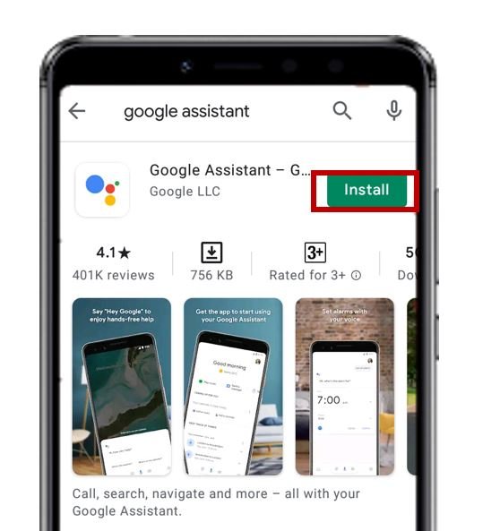
We will use an Android smartphone for this project. So go to Google Play. Search for ‘Google Assistant’ and install the application.
Now open your Google Assistant app on your smartphone. Make sure your Google Assistant is connected with the same email as your Adafruit IO and IFTTT account.
Touch the microphone icon and say ‘Turn LED ON’ or ‘LED ON’ and the onboard LED will light up.
Likewise, say ‘Turn LED OFF’ or ‘LED OFF’ and the onboard LED will turn OFF.
The Google Assistant will also display a message after each updating process.

The serial monitor will also print relevant messages as the state of the LED gets updated.

Conclusion
To sum up, this article has shown how to use ESP32 with Google Assistant and Adafruit IO. This lets you control things using your voice with Google Assistant and track data with Adafruit IO. By following the steps and examples provided, you can create cool projects that combine voice control and data monitoring. This is a great example of how technology can come together to make smart and interactive systems.
You may also like to read:
good tutorial
Bonjour, Tu as fait un très bon travail et merci beaucoup pour le partage. J’ai essayé de refaire ce même travail et je suis parvenus à le reproduire et mon ESP32 répond parfaitement à commande vocales et le bouton sur IO-Adafruit réagit aussi aux commandes, sauf que au bout de quelques minutes l’ESP ne répond plus par contre sur le compte adafruitIO le bouton réagit au commandes vocales. Est-ce que vous avez une idée sur ce problème. Mais en tout cas Merci pour tout ce que vous faites sur ce site.