In this tutorial, we will learn how to control the output of ESP32 or ESP8266 NodeMCU by using Telegram Bot. Telegram is a free, cross-platform, cloud-based messaging application used for sending messages, videos, and images. For the user, it becomes extremely interactive as well as easy to use this application to control any AC appliance from anywhere over the internet. Only the Telegram application and a steady internet connection in your device (smartphone, laptop, tablet, etc.) are a requirement.
This in-depth guide provides the process of controlling GPIOs and LEDs of ESP32 and ESP8266 NodeMCU development boards from Telegram App using the Arduino IDE. In other words, we’ll learn how to establish seamless communication and remote control. Whether you’re a beginner or an experienced developer, this article provides step-by-step instructions and valuable insights to help you effectively harness the potential of ESP32 and ESP8266 for IoT projects and beyond.
For this Telegram tutorial, we will keep it simple and control the onboard LED of ESP32 or ESP8266 NodeMCU through Telegram using Arduino IDE. The led will be turned on or off by sending message commands from the Telegram bot to ESP32 or ESP8266 NodeMCU. But after doing this LED control tutorial, it will be relatively easy for you to control the relay with ESP32/ESP8266 and Telegram.
In this tutorial, we will learn the followings:
- What is Telegram?
- How to create a Telegram Bot to communicate with ESP32/ESP8266
- Send and receive messages to/from ESP32/ESP8266 using Telegram Bot
- Control GPIOs of ESP board with Telegram from anywhere in the world
Recommended Components
The following components are used in this project or are helpful for building it with the ESP32.
| Component | How it’s used in this project | Buy on Amazon |
|---|---|---|
| ESP32 Development Board (DevKit V1) | The main board that runs the project firmware. | Check Price |
| ESP8266 NodeMCU (ESP-12E) | An alternative Wi-Fi board; this tutorial works on the ESP8266 NodeMCU as well. | Check Price |
| Micro USB Cable | Connects the board to your computer to upload code and power it. | Check Price |
| Breadboard | Holds the board and components together while you wire up the project. | Check Price |
| Jumper Wires | Make the connections between the board and any external parts. | Check Price |
| 5mm LED | An external LED on a GPIO pin to test the on/off control from Telegram. | Check Price |
| Relay module | Switch a mains appliance instead of an LED using the same Telegram commands. | Check Price |
As an Amazon Associate we earn from qualifying purchases. Prices and availability are accurate as of the date/time indicated and are subject to change.
What is Telegram?
Telegram is a free-of-cost messaging application which allows users to send messages and make voice/video calls. It is available for different operating systems including Windows, macOS, Linux, Android, and Apple iOS. Additionally, it also has a feature for third-party developers to create bots.
These bots are set up without much hassle and can execute commands through cross-texting. They can also be invited into different groups and can be interfaced with any software program to trigger an event. We will use our ESP32 or ESP8266 module to interact with the bot. This will in return receive and handle the messages and send appropriate responses to the user.
ESP32/ESP8266 Telegram Project Overview
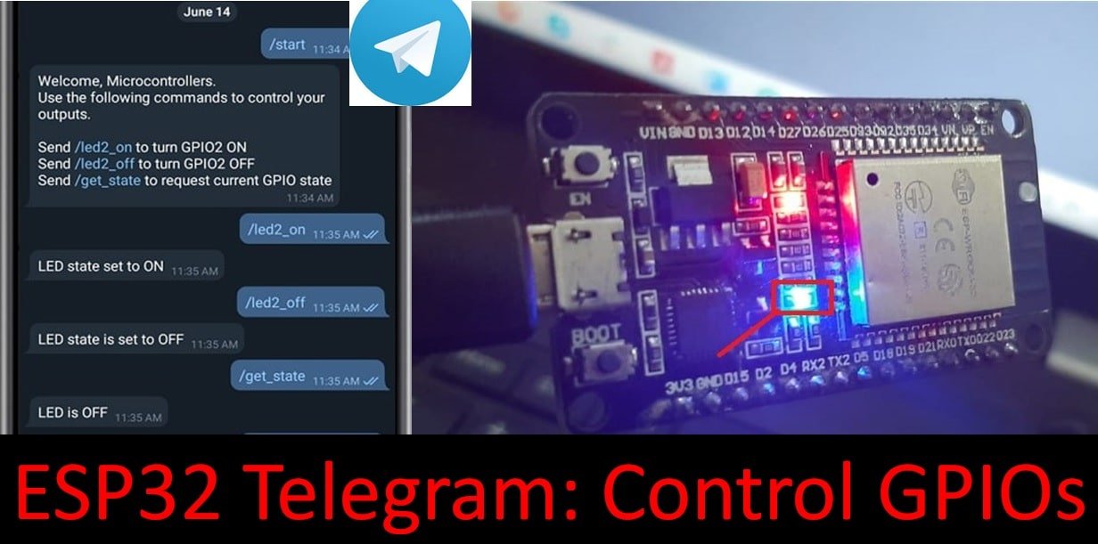
We will use Telegram to control the onboard LED of our ESP32 or ESP8266 development board. Firstly, we will install the Telegram application on our smartphone and then create a Telegram Bot for our ESP board. Secondly, we will use the bot token to start communicating with it. Then as we want to control the LED by toggling it, we will send a message to the bot to execute that particular command. Hence, the bot will receive the message and follow accordingly. The table below shows the messages we will send to the bot to execute upon.

| Commands | Description |
|---|---|
| /led2_on | This message will turn the onboard LED on. |
| /led2_off | This message will turn the onboard LED off. |
| /get_state | This message will send the current LED state (OFF or ON) to the telegram bot. |
| /start | This message will display a welcome message and the commands to control the ESP32/ESP8266 module to the user. |
Installing Telegram on your device
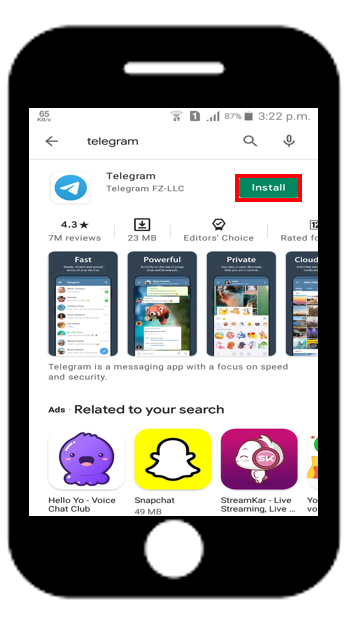
We will use an Android smartphone for this project. So go to Google Play or Apple Store (if using an iPhone).

Search for ‘Telegram’ and install the application.
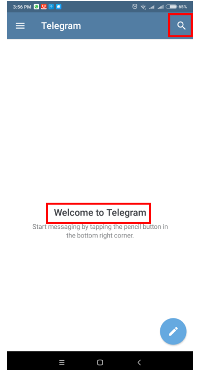
When the installation is finished open the application. You will get to view the Start Messaging button. Click it.

As you will be using this application for the first time a Sign Up is necessary. Complete the sign-up by giving in your smartphone number and country code as shown below.

Creating Telegram Bot
Open the Telegram app after you have successfully signed up. In the search option type ‘BotFather’.
Choose the one with the verified blue tick as shown in the picture below.

The following window will open up. Click the ‘Start’ button to proceed forward.

Now, type /newbot and send the message to the bot. This will create a new bot for us which we will use in our project.

Next, we will choose a name and username for our bot. You can type any name which you want. For the username you will have to try multiple names until an un-used valid name is chosen. Keep your username safe with you as your bot can be accessed through it.

You will receive a Congratulations message after your username gets accepted. Inside that message there will be a link through which you will be able to access your bot. Additionally, there will also be a bot token. This bot token will be used for the interaction between the ESP32/ESP8266 board and the Telegram bot.

Telegram User ID
Now, we will set up our Telegram user ID. This will be of immense help as it will filter out all unnecessary messages which we did not send or were not sent by an authorized user. This user id will be unique to a user and will help the ESP module to distinguish whether the message was sent by us or by someone else who was able to access our bot.
Open your Telegram app and go to the search tab. Write ‘IDBot’ and press enter.

The following window will open up. Send /getid command and you will receive your telegram user ID.

Install Telegram Arduino Library
Before we proceed further, you should make sure that you have the latest version of Arduino IDE installed on your system. Moreover, you should also install an ESP32 add-on or an ESP8266 add-on in Arduino IDE. For this project, we will have to install two libraries: the Universal Telegram Bot library and the ArduinoJson Library.
Installing Universal Telegram Bot Library
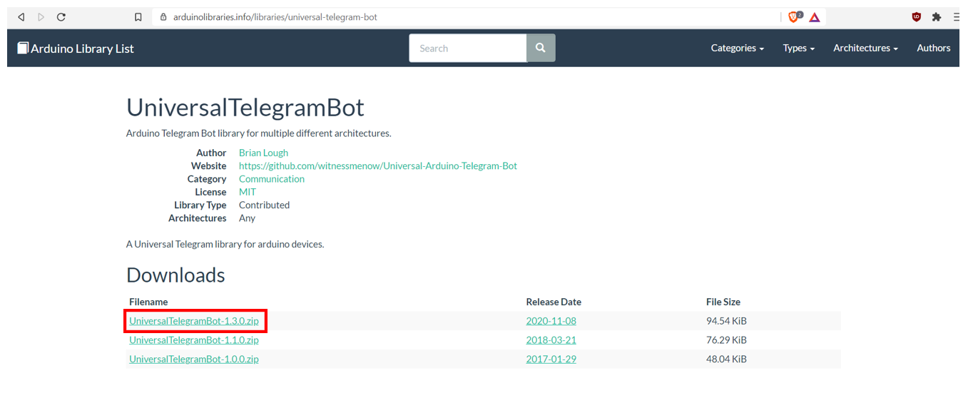
The Universal Telegram Bot library can be accessed by clicking here. Open this webpage and download the zip file highlighted in the red rectangular box. This library will help us in interacting with the telegram bot and providing us with a straightforward API.
After you have downloaded the .zip file, open your Arduino IDE. Go to Sketch > Include Library > Add .zip Library to add the library. After installation of the library, restart your IDE. We will not install the library from the Arduino Library Manager due to possible conflicting older versions.
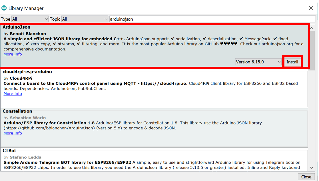
Installing ArduinoJson Library
To install the ArduinoJson library, open the IDE and go to Sketch > Include Library > Manage Libraries. Type ‘ArduinoJson’ in the search tab and press enter. Install the library that is highlighted in the red rectangular box.
ESP32 and ESP8266 Telegram Code
Open your Arduino IDE and go to File > New to open a new file. Copy the code given below in that file. This code will work for both ESP32 and ESP8266 development boards. You just have to replace the network credentials, bot token, and telegram user ID with your own values.
#ifdef ESP32
  #include <WiFi.h>
#else
  #include <ESP8266WiFi.h>
#endif
#include <WiFiClientSecure.h>
#include <UniversalTelegramBot.h>
#include <ArduinoJson.h>

// Replace with your network credentials
const char* ssid = "PTCL-BB";
const char* password = "********";

// Initialize Telegram BOT
#define BOTtoken "**********:***********************************"  // replace this with your bot token

#define CHAT_ID "**********"  //replace with your telegram user ID

#ifdef ESP8266
  X509List cert(TELEGRAM_CERTIFICATE_ROOT);
#endif

WiFiClientSecure client;
UniversalTelegramBot bot(BOTtoken, client);

// Checks for new messages every 1 second.
int bot_delay = 1000;
unsigned long lastTimeBotRan;

const int ledPin = 2;
bool ledState = LOW;

// Handle what happens when you receive new messages
void handleNewMessages(int numNewMessages) {
  Serial.println("Handling New Message");
  Serial.println(String(numNewMessages));

  for (int i=0; i<numNewMessages; i++) {
    // Chat id of the requester
    String chat_id = String(bot.messages[i].chat_id);
    if (chat_id != CHAT_ID){
      bot.sendMessage(chat_id, "Unauthorized user", "");
      continue;
    }

    // Print the received message
    String user_text = bot.messages[i].text;
    Serial.println(user_text);

    String your_name = bot.messages[i].from_name;

    if (user_text == "/start") {
      String welcome = "Welcome, " + your_name + ".\n";
      welcome += "Use the following commands to control your outputs.\n\n";
      welcome += "Send /led2_on to turn GPIO2 ON \n";
      welcome += "Send /led2_off to turn GPIO2 OFF \n";
      welcome += "Send /get_state to request current GPIO state \n";
      bot.sendMessage(chat_id, welcome, "");
    }

    if (user_text == "/led2_on") {
      bot.sendMessage(chat_id, "LED state set to ON", "");
      ledState = HIGH;
      digitalWrite(ledPin, ledState);
    }

    if (user_text == "/led2_off") {
      bot.sendMessage(chat_id, "LED state is set to OFF", "");
      ledState = LOW;
      digitalWrite(ledPin, ledState);
    }

    if (user_text == "/get_state") {
      if (digitalRead(ledPin)){
        bot.sendMessage(chat_id, "LED is ON", "");
      }
      else{
        bot.sendMessage(chat_id, "LED is OFF", "");
      }
    }
  }
}

void setup() {
  Serial.begin(115200);

  #ifdef ESP8266
    configTime(0, 0, "pool.ntp.org");      // get UTC time via NTP
    client.setTrustAnchors(&cert); // Add root certificate for api.telegram.org
  #endif

  pinMode(ledPin, OUTPUT);
  digitalWrite(ledPin, ledState);

  // Connect to Wi-Fi
  WiFi.mode(WIFI_STA);
  WiFi.begin(ssid, password);
  #ifdef ESP32
    client.setCACert(TELEGRAM_CERTIFICATE_ROOT); // Add root certificate for api.telegram.org
  #endif
  while (WiFi.status() != WL_CONNECTED) {
    delay(1000);
    Serial.println("Connecting to WiFi..");
  }
  // Print ESP32 Local IP Address
  Serial.println(WiFi.localIP());
}

void loop() {
  if (millis() > lastTimeBotRan + bot_delay)  {
    int numNewMessages = bot.getUpdates(bot.last_message_received + 1);

    while(numNewMessages) {
      Serial.println("Got Response!");
      handleNewMessages(numNewMessages);
      numNewMessages = bot.getUpdates(bot.last_message_received + 1);
    }
    lastTimeBotRan = millis();
  }
}
How does the Code Work?
Including Libraries
We will start by including all the necessary header files which are required for ESP32 and ESP8266 to send and receive notifications from telegram. As this code is compatible with both ESP32 and ESP8266, therefore, both libraries WiFi.h and ESP8266WiFi.h) are defined. As a result, this library will help in establishing the connection between our ESP modules to a wireless network. We will also include the two libraries which we installed previously, the Universal Telegram Bot library and the ArduinoJson library.
#ifdef ESP32
  #include <WiFi.h>
#else
  #include <ESP8266WiFi.h>
#endif
#include <WiFiClientSecure.h>
#include <UniversalTelegramBot.h>
#include <ArduinoJson.h>
Setting Network Credentials
Next, we will create two global variables, one for the SSID and the other for the password. These will hold our network credentials which will be used to connect to our wireless network. Replace both of them with your credentials to ensure a successful connection.
const char* ssid = "PTCL-BB"; //replace with your SSID
const char* password = "********"; //replace with your password
Setting Output Variables
Then, we will define the variable ledPin to save the GPIO pin through which the on-board LED will be connected i.e., GPIO2. The ‘ledState’ variable will be used to store the current LED state. We will initialize it as LOW because initially, the LED will be off for ESP32 and on for ESP8266.
For ESP8266, the on-board LED works on an opposite logic as compared to ESP32. To turn the onboard LED ON, a low signal is sent and to turn it OFF, a high signal is sent. This is opposite in the case of ESP32.
| Onboard LED ON | Onboard LED OFF | |
|---|---|---|
ESP32 | State: HIGH (1) | State: LOW (0) |
ESP8266 | State: LOW (0) | State: HIGH (1) |
const int ledPin = 2;
bool ledState = LOW;
Specifying Bot Token and Telegram User ID
Next up is a very important step. You will have to specify your bot token to establish a successful connection between the ESP board the telegram bot as well as the Telegram user ID. To access your bot token, open your Telegram application and go to BotFather. You will be able to view your bot token in the congratulatory message there. Copy it carefully in the program code. Next, to distinguish unauthorized users we will also add our Telegram user ID. You can access it through the IDBot.
#define BOTtoken "**********:***********************************"  // replace this with your bot token

#define CHAT_ID "**********"  //replace with your telegram user ID
Creating WIFI Client
Then we will create a new WiFi client of the WiFiClientSecure library. By specifying the bot token and the new client which we created before, we will create a new bot by accessing the Universal Telegram Bot library. The bot_delay variable will check for new messages after a specified number of milliseconds. We have specified 1000 milliseconds which means that after every second the ESP board will check for any new message received.
WiFiClientSecure client;
UniversalTelegramBot bot(BOTtoken, client);
Adding Delay
The bot_delay variable will check for new messages after a specified number of milliseconds. We have specified 1000 milliseconds. As a result, after every second the ESP board will check for any new message received.
int bot_delay = 1000;
unsigned long lastTimeBotRan;
Handling New Messages
Next, we will define the handleNewMessages function. This takes in a single parameter of type int named numNewMessages. This function will be called whenever a new message is received.
void handleNewMessages(int numNewMessages) {
  Serial.println("Handling New Message");
  Serial.println(String(numNewMessages));
For every message that is received its chat id (Telegram user ID) gets saved in the variable chat_id. Then it checks whether this id matches with the user chat id which was initially defined in the code. If both the ids do not match it means an unauthorized user sent the message. Thus, the bot will specify to us that it was an unauthorized user through bot.sendMessage() and will move on to the next message instead. If both the chat ids match then it means that the rightful user sent the message and it will get saved in the variable user_text.
for (int i=0; i<numNewMessages; i++) {
    // Chat id of the requester
    String chat_id = String(bot.messages[i].chat_id);
    if (chat_id != CHAT_ID){
      bot.sendMessage(chat_id, "Unauthorized user", "");
      continue;
    }
// Print the received message
String user_text = bot.messages[i].text;
Serial.println(user_text);
String your_name = bot.messages[i].from_name;This message will get saved in the variable user_text and will get printed on our serial monitor. Moreover, we will also save the name of the sender in the variable your_name. This will be used later to display the Welcome message.
Commands Execution
Now we will define and handle the different commands which we will send to our telegram bot. We will be sending in a total of four commands: /start, Turn LED ON, Turn LED OFF, and Give State.
Welcome Message
Firstly, if we send the /start command to the bot then a series of Welcome message will be displayed to us. We will receive a message displaying all the commands which we can use to control our ESP32 or ESP8266 board. This will be accomplished by using the sendMessage() method on the bot object like this: bot.sendMessage(). The chat id, the Welcome text, and an empty string will be passed as parameters inside it.
In our case: bot.sendMessage(chat_id, welcome, “”)
if (user_text == "/start") {
      String welcome = "Welcome, " + your_name + ".\n";
      welcome += "Use the following commands to control your outputs.\n\n";
      welcome += "Send /led2_on to turn GPIO2 ON \n";
      welcome += "Send /led2_off to turn GPIO2 OFF \n";
      welcome += "Send /get_state to request current GPIO state \n";
      bot.sendMessage(chat_id, welcome, "");
    }
Turn LED ON
Secondly, if we send the Turn LED ON command, the onboard LED will turn On. First, we will receive a message from the bot “LED state is set to ON”. Then the state will be set to a HIGH value. By using the digitalWrite() function, the onboard led will turn On by passing the GPIO PIN 2 (ledPin) and the state (ledState) inside the function.
*For ESP8266 board: To turn the onboard LED On, make sure to set the ledState variable to LOW as it works on an inverted logic.
if (user_text == "/led2_on") {
      bot.sendMessage(chat_id, "LED state set to ON", "");
      ledState = HIGH;
      digitalWrite(ledPin, ledState);
    }
Turn LED OFF
Thirdly, if we send the Turn LED OFF command, the onboard LED will turn Off. First, we will receive a message from the bot “LED state is set to OFF”. Then the state will be set to a LOW value. By using the digitalWrite() function, the onboard led will turn Off by passing the GPIO PIN 2 (ledPin) and the state (ledState) inside the function.
*For ESP8266 board: To turn the onboard LED Off, make sure to set the ledState variable to HIGH as it works on an inverted logic.
if (user_text == "/led2_off") {
      bot.sendMessage(chat_id, "LED state is set to OFF", "");
      ledState = LOW;
      digitalWrite(ledPin, ledState);
    }
Give State
Finally, if we send the Give State command the current GPIO state will be displayed as either ON or OFF. Through digitalRead() function GPIO2 will be accessed and relevant messages will be displayed accordingly. Either “LED is ON” or “LED is OFF”.
if (user_text == "/get_state") {
      if (digitalRead(ledPin)){
        bot.sendMessage(chat_id, "LED is ON", "");
      }
      else{
        bot.sendMessage(chat_id, "LED is OFF", "");
      }
Setup()
Inside the setup() function, we will start the serial connection at a baud rate of 115200.
Serial.begin(115200);For ESP8266 some additional lines of code will also be added as shown below:
#ifdef ESP8266
    configTime(0, 0, "pool.ntp.org");      // get UTC time via NTP
    client.setTrustAnchors(&cert); // Add root certificate for api.telegram.org
  #endif
Using the pinMode() function, we will configure GPIO2 through which the onboard Led is connected as an output pin. This will be set to LOW initially at the time of boot.
pinMode(ledPin, OUTPUT);
digitalWrite(ledPin, ledState);
Connecting with WIFI
The following section of code will connect our ESP32/ESP8266 board with the local network whose network credentials we already specified above. After the connection will be established, the IP address of the ESP32 board will get printed on the serial monitor.
WiFi.mode(WIFI_STA);
  WiFi.begin(ssid, password);
  #ifdef ESP32
    client.setCACert(TELEGRAM_CERTIFICATE_ROOT); // Add root certificate for api.telegram.org
  #endif
  while (WiFi.status() != WL_CONNECTED) {
    delay(1000);
    Serial.println("Connecting to WiFi..");
  }
  Serial.println(WiFi.localIP());
loop()
Inside the loop() function new messages will be checked after every second. Whenever a new message will be received the handleNewMessages() function will be called.
while(numNewMessages) {
  Serial.println("Got Response");
  handleNewMessages(numNewMessages);
  numNewMessages = bot.getUpdates(bot.last_message_received + 1);
}
Demonstration
Make sure you choose the correct board and COM port before uploading your code to the board. Therefore go to Tools > Board and select ESP32 Dev Module or ESP8266 Module.
If you are using ESP32, select the ESP32 Dev module as follows:

If you are using ESP8266 NodeMCU, select the NodMCU module as follows:
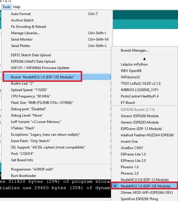
Then, go to Tools > Port and select the appropriate port through which your board is connected.

Click on the upload button to upload the code to ESP32 or ESP8266 development board.
After you have uploaded your code to the ESP32 or ESP8266 development board, press its ENABLE button.

ESP8266 NodeMCU reset button:

In your Arduino IDE, open up the serial monitor and you will see that the IP address will be assigned to ESP32/ESP8266 connects to the internet, and all observer what shows on the serial monitor when we send control commands from the telegram bot.
Now open your Telegram application on your smartphone. Go to BotFather and access the bot you created by following the link provided there as follows:

Type /start and press enter to send it to your newly created bot. As a result, this will show you a welcome message from the bot. All the different commands will be displayed which you can enter one by one.

- Send /led2_on to turn GPIO2 ON
- Send /led2_off to turn GPIO2 OFF
- Send /get_state to request the current GPIO state
The bot will respond to each command accordingly. The serial monitor will also continuously give updates after each command is executed.
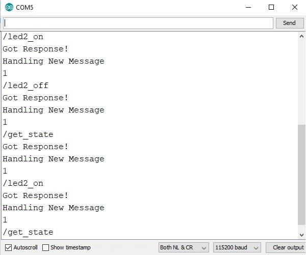
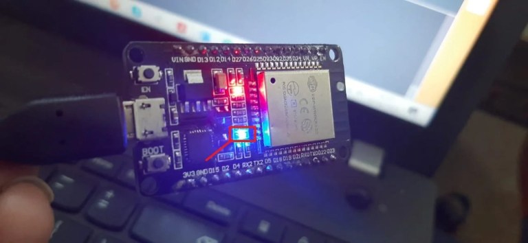
Similarly, the onboard LED of ESP32 will turn on when we send /led2_on command and will turn off when we send the led2_off message from telegram to ESP32. The opposite logic works for ESP8266 NodeMCU.
In conclusion, we learned how to control the output GPIO of the ESP development board through a Telegram bot. Through Telegram it is very convenient to control any home appliances, relay, etc, from anywhere in the world.
In this tutorial, we have learned to control GPIO pins with a telegram bot. But we can use it to request sensor data, get pictures from ESP32-CAM, and for many other applications.
If you want to send sensor readings from ESP32 and ESP8266 NodeMCU to the Telegram app, you can follow this tutorial:
You may also like to read these:
Telegram User ID does not exist to find Telegram ID. How else can I find it?
Solved
Im using nodemcu with esp 8266 my instaled board version is 2.5.2. i make evryting step by step like in touturial and im not reciving messege from my bot. In serial monitor is only ip. adress. Can somone help my?
Please check if you have defined these correctly:
// Initialize Telegram BOT
#define BOTtoken “**********:***********************************” // replace this with your bot token
#define CHAT_ID “**********” //replace with your telegram user ID
Thanks for respons, I found Solution. My router was blocking esp
Good to hear that. Blocking the IP of your ESP board?
Yes, because I self did that in Setup menu of my router couple month ego 😀 Thx for good tutorial
Good to know that our tutorial helped you.
Is there any way to allow 2 Telegram accounts / users to access the same ESP32?
I have researched for days but cannot find a solution.