Imagine being able to control things like lights or appliances in your home from your phone, no matter where you are. In this tutorial, we will learn how to receive data from Google Firebase. We will send data from Google Firebase to ESP32. In response to that data, we will control the onboard LED of the ESP32. Firstly, we will see how to set up Firebase and install Arduino Library for Firebase. After that, we will see an ESP32 code to get data from this real-time database.
Alternatively, you can also use two ESP32 boards. One will send data to Firebase and the other ESP32 will read data from a real-time database. Based on this received data, users can perform various actions such as controlling outputs, reading sensor data, etc.
You can also read this guide where we have learned to send sensor readings to Google Firebase and Andriod app reads that data and display it:
Previously, we have seen multiple ways through which we could control the ESP32 GPIO outputs. You can view the tutorials by accessing the links below.
- Telegram ESP32 and ESP8266: Control GPIOs and LEDs using Arduino IDE
- ESP32/ESP8266 Web Server to Control Outputs with a Timer (Pulse Width)
- ESP32 WebSocket Server using Arduino IDE – Control GPIOs and Relays
- ESP32/ESP8266 Momentary Switch Web Server: Control GPIO Outputs

This time, we will show you another great application through which we will be able to control any output connected to the ESP32’s GPIO pins. For simplicity purposes, we will toggle the onboard LED of the development board, but you can use any other device such as a relay, buzzer, DC motor, etc.
This article is divided into these sub-topics:
- Introduction of Google Firebase
- Setting up Google Firebase Console
- Getting Arduino IDE ready
- Simple project using ESP32, Arduino IDE, and Google Firebase application.
Recommended Components
The following components are used in this project or are helpful for building it with the ESP32.
| Component | How it’s used in this project | Buy on Amazon |
|---|---|---|
| ESP32 Development Board (DevKit V1) | Runs the firmware that receives data from Google Firebase to control its outputs. | Check Price |
| Micro USB Cable | Connects the board to your computer to upload the sketch and power it. | Check Price |
| Breadboard | Holds the board and components together while you wire up the project. | Check Price |
| Jumper Wires | Make the connections between the board and any external parts. | Check Price |
| 5mm LED | An external LED on a GPIO pin to visualise the output controlled from Firebase. | Check Price |
As an Amazon Associate we earn from qualifying purchases. Prices and availability are accurate as of the date/time indicated and are subject to change.
Google Firebase Introduction
Google Firebase is an application development software created by Google. It can be used with any Android/iOS application, IoT sensors, and web services to create and alter the data obtained from them. It is a helpful software for building mobile/web applications easily and interactively. Paid services include a real-time database, Firebase storage, hosting, and test lab. However, you can use Analytics for advanced messaging for free, although you will have to create an account before accessing it.
One of the significant attributes of this software is that it is beginner friendly. It is very simple to connect your application to Google Firebase. You have to follow each step carefully. If you have any difficulty or want to access further information, take a look at the official Google Firebase Documentation.
Setting up Google Firebase Console
Before proceeding with the project let us understand the steps which have to be followed to successfully connect with the Google Firebase application.
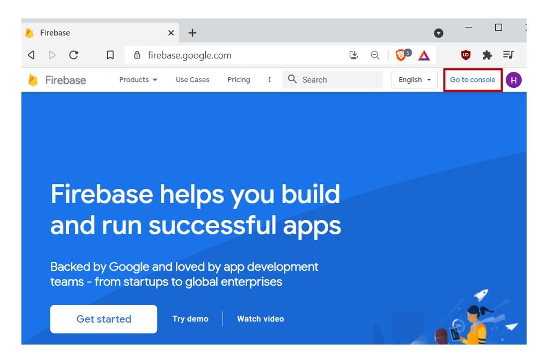
Firstly, type https://firebase.google.com/ in your browser search tab and press enter.
This will open the Firebase main page. Click ‘Go to Console’ as highlighted in the red rectangular box.
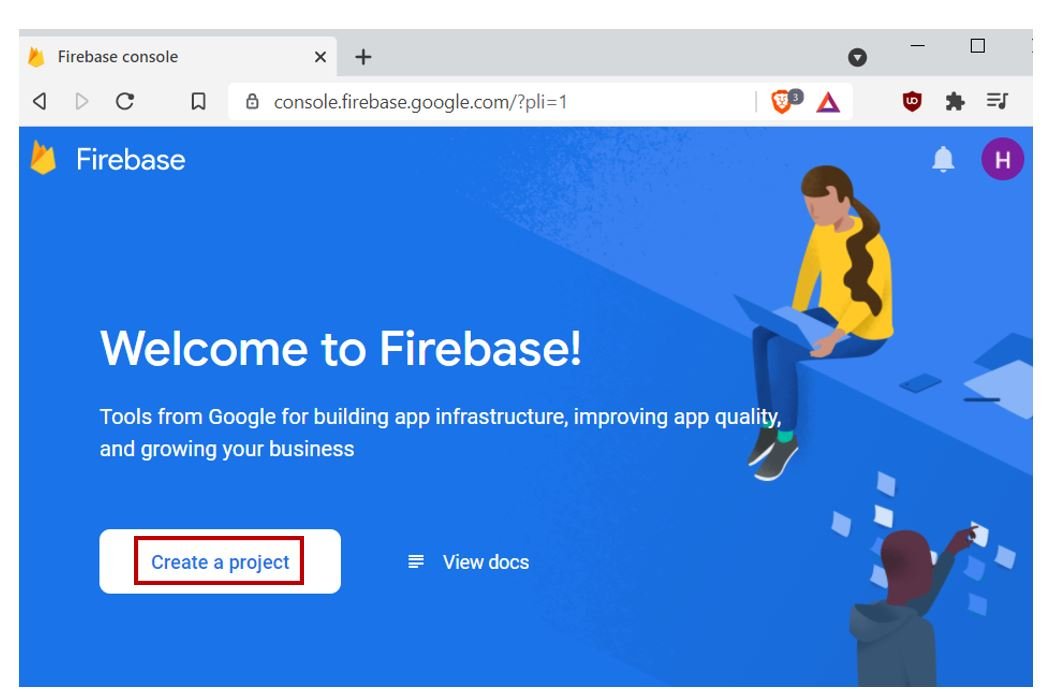
You will be redirected to a new web page with the welcome message. Click the button ‘Create a Project’ as shown below.
The following page opens up.
Step 1: Write the name of your project. Remember to tick the Firebase term agreement. Now click ‘Continue’.

Step 2: Now enable ‘Google Analytics for this project’ by swiping the sliding button. Click ‘Continue’ to proceed further.

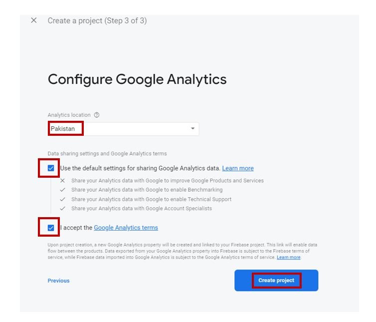
Step 3: After choosing your location and ticking the required boxes click ‘Create Project’.
After a few moments, your project will be created.
Click ‘Continue’

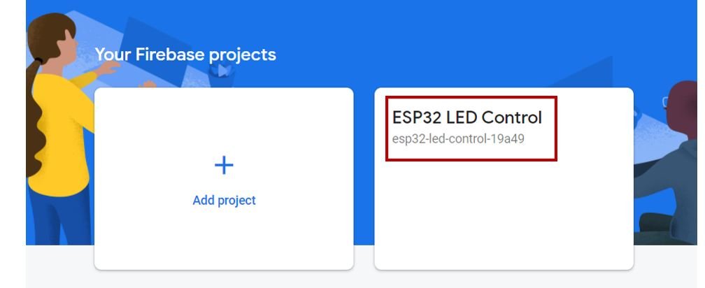
You will be redirected to the main page which will now contain your newly created project. Click on it.
Obtaining Authorization key and Firebase host
In the top left corner of the web page, click on the three horizontal bars.

Next, go to the settings icon and click ‘Project Settings’.

Now, go to ‘Service Accounts’ and click ‘Generate new private key’.

Then go to ‘Database secrets.’ You will be able to view a secret key associated with your project. This is the unique authorization key that you will save and use later on in the program code. Keep it a secret and do not share it with anyone or your project security will be compromised.

Next, Under the Build tab go to ‘Realtime Database.’ Then click ‘Create Database.’
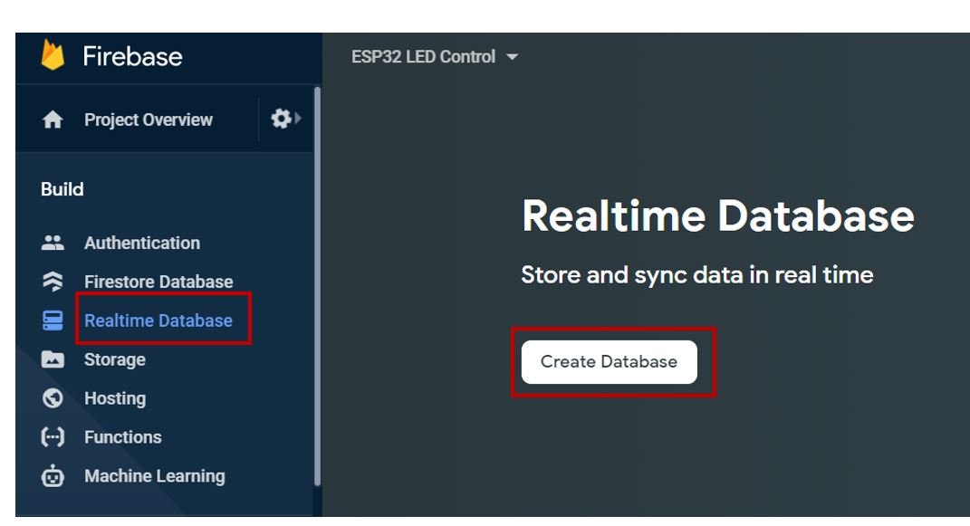
After setting your location, check ‘Start in Test mode’ and then click the Enable button.

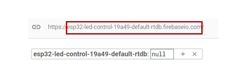
Your database settings are completed. Copy the text shown in the highlighted box below. Save it as well. This will act as your Google Firebase host which we will incorporate in our program code.
Installing Google Firebase ESP32 Library
We will use Arduino IDE to program our ESP32 development board. Thus, you should have the latest version of Arduino IDE. Additionally, you also need to install the ESP32 plugin. If your IDE does not have the plugin installed you can visit the link below:
Installing ESP32 library in Arduino IDE and uploading code
In order to use Google Firebase with our ESP32 board, we would have to install its library in our Arduino IDE.
To download the library, click here. Click on ‘Code’ and then ‘Download Zip’.

You will download the library as a .zip folder which you will extract and rename as ‘IOXhop_FirebaseESP32.’ Then, transfer this folder to the installation library folder in your Arduino IDE.
Likewise, you can also go to Sketch > Include Library > Add .zip Library inside the IDE to add the library as well. After installation of the library, restart your IDE.
For this library to work properly make sure you have the ArduinoJson library 5.13.3 version installed in your Arduino IDE. To check go to Tools > Sketch > Manage Libraries.

ESP32 Google Firebase Code
Open your Arduino IDE and go to File > New to open a new file. Copy the code given below in that file. You need to enter your network credentials. Additionally, you also have to provide your Authorization key and the Google Firebase Host both of which we saved previously.
#include <WiFi.h>
#include <IOXhop_FirebaseESP32.h>

#define FIREBASE_Host "esp32-led-control-19a49-default-rtdb.firebaseio.com"                   // replace with your Firebase Host
#define FIREBASE_authorization_key "Jgq6M6eeyqurhOCL0FB7Mq4Rlat3a6Hcg1*******" // replace with your secret key
#define Your_SSID "Write_your_SSID"       // replace with your SSID
#define Your_PASSWORD "*********"          //replace with your Password

String led_state = "";                                                     // LED State
int led_gpio = 2;

void setup() {

  Serial.begin(115200);
  delay(1000);
  pinMode(2, OUTPUT);
  WiFi.begin(Your_SSID, Your_PASSWORD);
  Serial.print("Connecting to WIFI");
  while (WiFi.status() != WL_CONNECTED) {
  Serial.print(".");
  delay(500);
  }

  Serial.println();
  Serial.print("Connected to WIFI!");
  Serial.println();
  Serial.print("IP Address: ");
  Serial.println(WiFi.localIP());                                                      //print local IP address
  Firebase.begin(FIREBASE_Host, FIREBASE_authorization_key);                                       // connect to firebase
  Firebase.setString("LED State: ", "OFF");                                          //send initial string of led status

}

void loop() {

  led_state = Firebase.getString("LED State: ");
  if (led_state == "ON") {

    Serial.println("Led is ON");
    digitalWrite(led_gpio, HIGH);

  }

  else if (led_state == "OFF") {

    Serial.println("Led is OFF");
    digitalWrite(led_gpio, LOW);

  }

  else {
     Serial.println("Wrong value entered! Only ON or OFF accepted");

  }

}
How does the Code Work?
Including Libraries
Firstly, we will include the necessary libraries required for this project. WiFi.h will help in establishing the connection between the ESP32 module to a wireless network. We will also include the library which we installed previously, for the Firebase functionality.
#include <WiFi.h>
#include <IOXhop_FirebaseESP32.h>
Defining Firebase credentials
Secondly, we will define the Google Firebase host and authorization key which we accessed and saved previously.
#define FIREBASE_Host "esp32-led-control-19a49-default-rtdb.firebaseio.com"               // replace with your Firebase Host
#define FIREBASE_authorization_key "Jgq6M6eeyqurhOCL0FB7Mq4Rlat3a6Hcg1l*****" // replace with your secret key
Defining Network credentials
Next, we will define the network credentials. One for the SSID and the other for the password. These will be our network credentials which will be used to connect to our wireless network. Replace both of them with your credentials to ensure a successful connection.
#define Your_SSID "Write_your_SSID_here"   // replace with your SSID
#define Your_PASSWORD "********"          //replace with your Password
Defining Variables
Then, we will define the variable led_state which will save the current state of the LED (ON/OFF). Initially, it is defined as an empty string.
Another variable of data type int called ‘led_gpio’ will save the GPIO pin through which the onboard LED is connected i.e., GPIO2.
String led_state = "";
int led_gpio = 2;
Setup() function
Inside the setup() function, we will open a serial connection at a baud rate of 115200.
Serial.begin(115200);By using the pinMode() function, the ‘led_gpio’ variable (GPIO2) will be passed as a parameter inside the function which will be configured as the output pin.
pinMode(led_gpio, OUTPUT); The following section of code will connect our ESP32 board with the local network whose network credentials we already specified above. We will use the WiFi.begin() function. The arguments will be the SSID and the password which we defined earlier in the code. After the connection will be established, the IP address of the ESP board will get printed on the serial monitor.
  WiFi.begin(Your_SSID, Your_PASSWORD);
  Serial.print("Connecting to WIFI");
  while (WiFi.status() != WL_CONNECTED) {
  Serial.print(".");
  delay(500);
  }
  Serial.println();
  Serial.print("Connected to WIFI!");
  Serial.println();
  Serial.print("IP Address: ");
  Serial.println(WiFi.localIP());
Now, we will connect our ESP32 module with Google Firebase by using the Firebase.begin() function. It takes in two parameters. The first is the Firebase host and the second is the authorization key. Both were defined earlier on in the program code. Through correct credentials, a successful connection will be made.
Firebase.begin(FIREBASE_Host, FIREBASE_authorization_key); Next, we will use the Firebase.setString() function. We are passing two string arguments inside it. These will be sent to the Firebase server. Initially, we are setting the second argument as ‘OFF’ which we will be able to change ourselves by either typing ‘ON’ or ‘OFF’. As a result, it will toggle the onboard LED.
Firebase.setString("LED State: ", "OFF"); loop() function
We will save the state of the led in the variable ‘led_state’ by using Firebase.getString(). The first argument of the Firebase.setString() function will be passed as a parameter inside it. Thus, the ‘led_state’ will save the state of the LED.
led_state = Firebase.getString("LED State: "); By using the if-else statement we will check whether the saved state is ‘ON’ or ‘OFF’. If it is ‘ON’ then the onboard LED will turn ON. This will be achieved by using the digitalWrite() function. We will pass led_gpio and HIGH as the parameters inside it. Thus, the state of GPIO2 will turn high and the LED lights up. Additionally, ‘LED is ON’ also gets displayed on the serial monitor.
  if (led_state == "ON") {
    Serial.println("Led is ON");
    digitalWrite(led_gpio, HIGH);
  }
Likewise, if the current saved state is ‘OFF’ then the onboard LED will turn OFF. This will be achieved by using the digitalWrite() function. We will pass led_gpio and LOW as the parameters inside it. Thus, the state of GPIO2 will turn low and the LED turns off. Additionally, ‘LED is OFF’ also gets displayed on the serial monitor.
else if (led_state == "OFF") {
    Serial.println("Led is OFF");
    digitalWrite(led_gpio, LOW);
  }
This is the error message that will get displayed on the serial monitor if the user enters anything other than ‘ON’ or ‘OFF’.
else {
     Serial.println("Wrong value entered! Only ON or OFF accepted");
     }
Demonstration
Make sure you choose the correct board and COM port before uploading your code to the board. Go to Tools > Board and select ESP32 Dev Module.

Next, go to Tools > Port and select the appropriate port through which your board is connected.

Click on the upload button to upload the code to your ESP32 development board.
After you have uploaded your code to the development board, press its ENABLE button.

In your Arduino IDE, open up the serial monitor and you will be able to see the status of your WIFI connection and the IP address of your ESP module. Initially, we set the onboard LED to a LOW state so it will be OFF. This also gets printed on the serial monitor.

Now, open your Firebase console and go to the project settings of your current project. Open the Real-time Database. You will be able to view the LED status as OFF. You can change it to ‘ON’ and press enter. Simultaneously, the onboard LED will turn ON.


The serial monitor will also display ‘LED is ON’. Likewise, you can control the LED by changing the state in the database and it will update accordingly.

Google Firebase key Features
Here are some key components and features of Google Firebase:
Real-time Database: Firebase provides a real-time cloud database that allows developers to store and sync data across different devices in real-time. This is particularly useful for applications that require instant updates, such as messaging apps or collaborative tools.
Authentication: Firebase offers built-in authentication services, allowing developers to easily implement user authentication using email/password, social media logins (like Google and Facebook), and more.
Cloud Functions: Developers can write serverless functions that automatically trigger based on events in the application, such as when new data is added to the database. This can be used for tasks like sending notifications or processing data.
Cloud Storage: Firebase provides cloud storage for hosting and serving static assets like images, videos, and files. It’s a scalable solution for managing media assets in your application.
Hosting: Firebase Hosting allows developers to deploy and host web applications quickly and securely. It also supports automatic SSL certificates, making it easy to set up secure connections for your applications.
Machine Learning: Firebase includes machine learning capabilities, such as image recognition and language processing, that developers can integrate into their applications without needing extensive AI expertise.
Analytics: Firebase Analytics provides insights into how users are interacting with your app, helping you understand user behavior, retention rates, and other key metrics.
Remote Config: This feature allows you to dynamically update app settings and content without requiring users to update the app itself. It’s useful for making adjustments without releasing new versions of the app.
Notifications: Firebase Cloud Messaging (FCM) enables you to send notifications and messages to users across different devices, helping you engage with your users effectively.
Overall, Google Firebase simplifies the development process by offering a suite of tools that handle various aspects of application development and management. It’s widely used by developers to create a wide range of applications, from simple mobile apps to complex web platforms.
Conclusion
In summary, the combination of Google Firebase and ESP32 microcontrollers brings significant advancement to the world of smart devices and home automation. This article showed us how to control ESP32 outputs with the help of Firebase’s real-time database capabilities. This means we can now easily make devices that can be controlled remotely, like turning lights on and off from a distance. This technology uses the internet to store and share data, allowing us to create more interactive and responsive applications for everyday tasks. As more and more devices become connected, this integration gives us exciting new ways to improve how we use technology in our lives. The article has provided us with a clear guide on using Firebase to connect ESP32 devices, opening doors to creative possibilities in the world of smart technology.