HT12E is an encoder IC for RF and IR modules mostly. It is a 12-bit decoder that uses 8-bits for address and 4 for data. RF and IR modules can interface with microcontrollers directly which requires a little bit complex programming. In addition, This encoder IC is easy to implement and simple to use. It comes in 18 and 20 pins. Both packages have only 18 functional pins. Furthermore, This encoder will use the logic states as data and address inputs. HT12E doesn’t work alone. It’s only an encoder and one side of communicator. On the contrary, the second part of the communicator uses an HT12D decoder. In short, HT12D is the most suitable decoder for HT12E because both are 12-bits and have the same number of address and data pins.
HT12E Encoder Pinout Diagram

Pin Configuration Description
Address Pins
| PINS | INTERNAL CONNECTIONS | DETAIL | |
|---|---|---|---|
| A0 | Pin 1 | CMOS Circuit with Input Pull-UP resistor and NMOS transmission gate with the protection of Diode | Pin1 to Pin 8 is the address pins. The logic state on these pins will set the 8-bit address. The 8-bit address comes with a total of 256 different combinations. Any of the combinations is useable as an address. Most of the time, all these pins attached to the ground or power which makes all the address bits the same. It is suitable in case of open communication. A specific address should be using secure communication. |
| A1 | Pin 2 | ||
| A2 | Pin 3 | ||
| A3 | Pin 4 | ||
| A4 | Pin 5 | ||
| A5 | Pin 6 | ||
| A6 | Pin 7 | ||
| A7 | Pin 8 | ||
Encoding and Power Pins
| PINS | INTERNAL CONNECTIONS | DETAIL | |
|---|---|---|---|
| VSS | Pin 9 | – | Pin 9 is a common ground pin of the encoder. The ground pin needs to attach with an external device to make it operatable with encoder. |
| AD8 | Pin 10 | CMOS Circuit with Input Pull-UP resistor and NMOS transmission gate with the protection of Diode | Pin 10 to pin 13 are the data pin of the encoder. The encoder transmits 12-bit data which has 8-bit of address and 4-bits of data. These pins are usable with any microcontroller or IC because only the logics state requires for data input on the data pins. |
| AD9 | Pin 11 | ||
| AD10 | Pin 12 | ||
| A11 | Pin 13 | ||
| TE’ | Pin 14 | CMOS Circuit with input Pull-UP high Resistors | Pin 14 is known as transmission enable pin. Transmission enable pin allows the data to transmit from data input to data output pins. It only acts as a switch which allows controlling the transmission of data with the use of external devices. |
| OSC2 | Pin 15 | – | Pin 15 is an oscillator output pin of the encoder. In HT12E there is an internal oscillator and it requires an external 1M resistor to operate which can be attached at OSC2 pin. An external oscillator is usable at the OSC2 pin. |
| OSC1 | Pin 16 | – | Pin 16 is an oscillator input pin of the encoder. OSC1 pin will use with the external oscillator input or the second terminal of the 1M resistor. |
| DOUT | Pin 17 | CMOS output signal | Pin 17 is a data output pin of HT12E. 12-bit data will come out from the DOUT pin and this pin will connect to the external transmission device. |
| VDD | Pin 18 | – | Pin 18 is a power input pin of the encoder. Voltages on this pin will make the IC functional. |
HT12E Encoder Features
- The encoder can encoder 4-word at a single time.
- CMOS technology makes the encoder a low noise immunity device.
- In HT12E builtin oscillator only requires a 5% resistor to operate.
- RF and IR modules can use directly with encoders.
- It is available in two packages, SOP and DIP.
- The encoder can convert 4-bit data to serial data.
HT12E Encoder Specifications
- The operating voltage range of the encoder is 2.4 to 12V.
- The encoder uses 0.1uA current with 5V at standby.
- Only 256 different combinations of addresses are usable with HT12E
HT12E Encoder Applications
- In remote control systems, this encoder is widely available for encoding the data for transmission.
- Recently IoT production has been increased very much. Most of the smart systems communicate with each other wirelessly which also has HT12E to avoid the load on the internet.
- Smoke and builder alarm system encoder their message by HT12E.
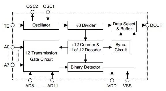
Block Diagram
The following diagram represents the internal structure of the HT12E.
HT12E Encode Working
The primary function of the encoder is to encode the 12-bit parallel input data and then forward it towards the output pin. In these 12-bits, 8 of them will come from the address pins and the rest of them will be from data input pins. The address pins are eight in numbers which describe the address of encoded signal. Most of the devices attached to the encoder only broadcast the signal. The broadcasted signal has an address that gets identified by the decoder to receive the data. The address is like a security for the communication system. In those cases where two receiving end or sending ends have the same address, then devices start messing with each other.
Data Pins
The next part is the data pins. These pins are 4 in number and these four pins describe the data in the encoded signal. The encoded signal gets the address and data in the form of logic states mostly. Due to the availability of microcontrollers and other smart devices the input signal can be applied through their GPIO pins. To use the encoder with external devices always check for their voltages otherwise the encoder can be destroyed.
How to use HT12E Encoder
The HT12E gives the ability to control the transmission with the external signals. Most of the time the control pin remains active but in special security cases, this can be controlled. The encoder signal always encodes with the oscillator speed. In HT12E there is an internal oscillator that requires an external 5% resistor but in case of the high-speed oscillator, these pins can attach with external oscillators. The output data of the encoder will be in serial form. This serial data can be sent through a wire or by any third device like IR of RF etc. To use the encoder the following general circuit is:

HT12E Encoder Example
In remote HT12E is widely available. You may notice that there are multiple buttons on the remote and each of them delivers a different function. Each button of the remote sends the different data input on the encoder and then the encoder passes it to the output pin. Sometimes you may notice that different devices remote doesn’t operate with each other, it is because of there specific address. These addresses make them operate with their desired devices. Here the IR transmitter circuit with encoder but the same circuit can be generated for RF just by replacing the IR transmitter.

Interfacing Example with Arduino
In addition to the above example circuit, You can also see this example on IR transmitter and receiver interfacing with Arduino.
- RF Transmitter and Receiver Module Interfacing with Arduino
- IR receiver-transmitter interfacing with Arduino
Security Issues
The HT12E uses the address to transmit with the transmitted data. This address can only be from 256 combinations of 8-bits. This makes the device limited. In most of the cases, the generated signal has a theft issue. Because the signal is broadcasted and unable to trace the receive. The address of the signal can be guessed by any receiver.
This address limitation makes the use of the HT12E suitable only at a shorter distance. At a shorter distance, the send and receiver can view each other, like the TV remote, Home Security, etc. In most of the cases, the address pins use the same logic state and work and avoid to take a complex address as an input. You may notice in commercial products, some remote control cars can be operated with a single remote at a time. Because they are designed for shorter distance and the company to avoid the complex address input and given the same address to all the devices.
2D Diagram
