Today in this article, we are going to introduce you to ULN2803 which is high current as well as high voltage Darlington transistor array. Usually, the chips being used operate on the low-level signals. Some of these chips are CMOS, NMOS, TTL, and PMOS. All these chips operate at either 0 volts or 5 volts thus these are not capable of driving loads of high inductive power. The ULN2803 chips take the low-level signals at input side i.e. TTL and make use of that low-level signal in switching off loads of higher voltage present at the output side. So in this article, we will discuss pin configuration of ULN2803, features as well as specification, how & where to use this and in the last, we will highlight some applications that are developed by using this chip. You may like to read:
INTRODUCTION TO ULN2803
The datasheet of ULN2803 specifies that this chip is a high current, high voltage Darlington transistor array. In this device, eight Darlington pairs of np-n configuration are present that have the feature of high voltage outputs along with the common-cathode clamp diodes that is used to switch inductive loads. The collector current rating for each np-n Darlington pair is about 500 mA. In order to achieve the higher capability of current, Darlington pairs of np-n configuration are connected in parallel.
ULN2803 pinout
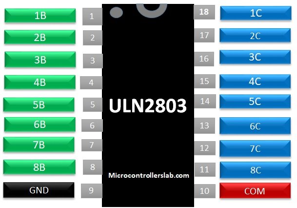
PIN CONFIGURATION OF ULN2803
In ULN2803, total numbers of pins are 18. The connection of these pins is as follow:
- Pin 1 is the base of first transistor.
- Pin 2 is the base of second transistor.
- Pin 3 is the base of third transistor.
- Pin 4 is the base of fourth transistor.
- Pin 5 is the base of fifth transistor.
- Pin 6 is the base of sixth transistor.
- Pin 7 is the base of seventh transistor.
- Pin 8 is the base of eighth transistor.
- Pin 9 is the emitter as well as ground of all transistors.
- Pin 10 is known as common pin i.e. node of common cathode which is used for the fly-back diodes.
- Pin 11 is the collector of eighth transistor.
- Pin 12 is the collector of seventh transistor.
- Pin 13 is the collector of sixth transistor.
- Pin 14 is the collector of fifth transistor.
- Pin 15 is the collector of fourth transistor.
- Pin 16 is the collector of third transistor.
- Pin 17 is the collector of second transistor.
- Pin 18 is the collector of first transistor.

ULN2803 FEATURES & SPECIFICATIONS
The specifications, as well as features of ULN2803, are as follow:
- The allowed maximum voltage between emitter & collector for each and every Darlington transistor is 50 volts.
- The maximum current that is allowed to flow through the collector of every Darlington pair is 500 mA.
- Between the emitter and base of the Darlington pair, the maximum voltage that is allowed is 30 volts.
- In each Darlington pair, a fly-back diode is present and the maximum current that is allowed to pass through that is 500 mA.
- The rise time is 130 ns.
- Typically, the fall time is 20micro-second.
- The operating temperature of ULN2803 lies in the range of -65°C – 150°C.
- In order to operate this chip, no additional power is needed.
WHERE & HOW TO USE ULN2803 MOTOR DRIVE IC
The ULN2803 chip can be used in the following cases:
- To control the inductive loads those are making use of the logic obtained by the control unit. In ULN2803, the Darlington array act as separate 8 individual switches and thus can be turned off and on as desired. Each set of these Darlington pair is capable of driving high power loads that use logic from the control unit.
- If you are willing to drive multiple loads, then this chip can be used as it is capable of driving eight loads at a time. However, the MOSFETs, as well as transistors that are being used in this chip, will suffice and also placing eight loads at the same time will be a cumbersome job but this chip is widely used in order to replace the bulk switching devices.
- This chip can also be used for programmable load sharing. if we are having one low power load as well as one high power load then multiple arrays can be connected in parallel in order to drive the high power load.
So, these are some of the most important scenarios in which ULN2803 can be used. But here the question arises that how we are going to use this chip. So in order to answer this question we have to look to the internal structure of ULN2803 given below. The each NOT gate present in the figure represents the Darlington transistor setup.
Internal circuit of ULN2803
As mentioned above, the ULN2803 chip comprises of 8 Darlington pairs that act as eight individual switches. Out of eight Darlington transistor pair, if we look at an individual pair then we can have something like this: 
The simplified Darlington pair can be shown as below:
From the above figures, it can be clearly seen that each Darlington pair can be used as the single power transistor. Thus, we can say that in ULN2803, eight power transistors are embedded. For better understanding, let’s look towards another circuit diagram to represent things in more comprehensive way:
Motor interfacing with ULN2803
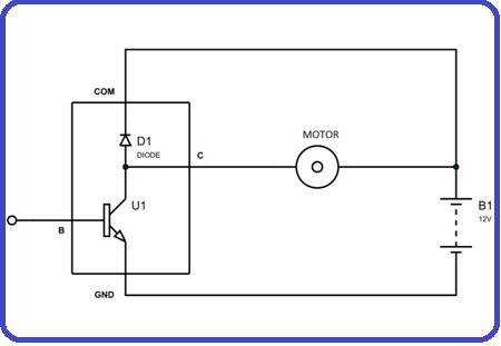
From this figure, it can be clearly seen that among eight transistor pairs, one pair is being used. The COLLECTOR of that Darlington transistor is connected to the motor. As we are already familiar that fly-back diodes are also present in each Darlington transistor thus the positive terminal of the battery is connected to the fly-back diode which is used to provide feedback to the motors’ inductive voltage spikes back to the voltage source. To the negative terminal of the battery, the ground i.e. Emitter is connected.
If we consider the normal situations, across the transistor, the complete voltage will appear whenever a motor will be turned off. However, when the power is supplied to the Base, then the transistor will be in ON state. Whenever the transistor is turned ON, the current will start flowing through the motor via Collector and ultimately it will reach the Emitter i.e. ground and the motor will start rotating depending on the flow of current.
If the power supplied to the Base is grounded, then in this case the transistor will turn off and thus the motor will stop working and in the same way, each Darlington transistor can be used to drive individual loads.
SWITCHING TIME OF ULN2803
The switching delays are not considered under normal conditions but whenever the switching frequency goes beyond 2 MHz the this needs to be considered and then two parameters need to be considered and these are
- Rise time
- Fall time
These delays must be considered in order to eliminate errors.
APPLICATIONS OF ULN2803
ULN2803 is widely used in the following applications:
- Hammer drivers
- Display drivers
- Logic Buffers
- Gas & LED discharger
- Logic buffers
- Relay drivers
- Lamp drivers
- Line drivers
So, in this article we looked at the pin layout, specifications & features of ULN2803, how & where to use this ULN2803, a simple circuit along with the explanation that how it is going to work as well as some of its applications. If you have any queries or comments regarding this article, then you can ask in the comment section below.
I have a 555/4017 board that I’m trying to drive a ULN2803 to power an LED array. Is the 4017 so “weak” that it cannot signal the ULN? I get no response from my circuit, past the indicator LEDs on my chaser board.
It has been awhile and I see no answer to you. Check the output on your 4017 with a scope. If you see it switching, but it’s output is too low, then add a pull up resistor to your circuit (i.e. get a resistor from your output of the 4017 to the power supply to pull up the output voltage)
Question 1. Would an ESP32, working at 3.3 V, with a logical HIGH value of about 2,3 V be capable to drive a ULN2803?
Question 2. Is there an equivalent of ULN2803 where GND and COM are exchanged (i.e., when the input triggers, I’d like to output GND) ?
Thanks in advance
I see no one has answered you.
Question 1: Depends on what the load is. If the EPS32, cannot drive the load through the ULN2803, try adding a pull up resistor to the ULN2803.
Question 2. Have you considered just adding an inverter to your circuit. The 74HCT04 inverter IC comprises six self-sustaining inverters with push and pulls outputs. You could put it on either the input or output.
Thx
thans for informaation 😉