Why we need UL2003 relay driver IC?
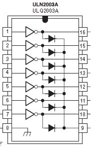
Working of ULN2003 IC

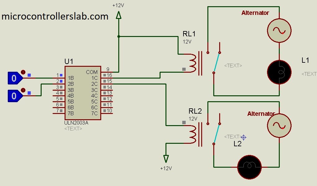
power supply is fed to this IC usually synthesis simulation software the ground is already given ground means the negative terminal negative terminal is already given to the IC here the positive terminal that is did relay will operate a 12 volt so this 12 volt is given to pin number 9 and this 12 volt is also given to the coil so what happens so this is high because this is 12 volt this is high and if this point goes low the current starts flowing and a relay will be activated but when will this go low this will go low when this becomes high similarly when this becomes high this will go low well let us first see before the first relay and let us now try to simulate and during the course we will also discuss about this relay and we will see what is the difference between this type of connection and this type of connection now we similar to this okay now we see there is a alternator here that you switch here the moment I switch on the power from the alternator let us see how this circuit is complete now first of all the power will flow this way this way this way pass through the lamp and stop here because this is open but in this situation for this lamp let us see what is happening the power will comes this way this way this way pass through this way this way the switch is closed it reaches this way the power has to start from this point and end at this point then the circuit is called circuit complete this lamp to grow that means the power should flow this way in this way this way this way this way this way this way this way this way this way this way this way I reach here unless it starts from here and reaches here
this circuit is not complete okay now let us see which lamp is glowing when I start simulation I switch on this you see this lamp is started going why because this path is complete mind it we are still not activated any of the relay because there is no current flowing in this relays because this is 0 this is 0 so this is 1 this is also 1 this is 1 and this also is 1 because I have connected this is also 2 12-volt connecting a coil this side 12 volt or the side 12 volt doesn’t make a difference okay now once we operate this relay once we make this logic from 0 to 1 you see what happens oh sorry yeah now what happens at this switch which was normally in this place has now switched over to this place so the path is complete now for this lamp also this is how the path is complex so this lamp is glowing but if I make this high what happens similarly this will also go to this side once this goes to the side what will happen the circuit will open and this lamp will stop let’s see ok
The lamp is stopped glowing because when this is high this is real high I said if when this is high this is low yes and the power flows this way on the power flows this way this relay is activated once this relay is activated this is this comes to this position like this this has come to this position this has come to this position let us see it frequently operating so that you can get an idea you see this see this see see I make it one zero one zero one zero okay now stop it now let make this zero see this one zero one zero one so like that this particular IC ul and 2003 has got seven such inputs at that means I can use seven relays in any combination at its output you see this output is a switch output means it’s not exactly output it is a switch and you can connect any external circuit any external circuit with any voltage particularly as per the rating of this switch if the switch rating is usually the switch rating that you will be using your project is about four amperes so you can put any load if this is a load you can put any load of four amperes it it could be a lamp it could be anything