In this tutorial, we will learn to interface MPU6050 MEMS module with Pic microcontroller. Firstly, we will see an introduction of MPU6050 such as pinout diagram, pin configuration, features, specifications. At the end, we will see how to interface the MPU6050 module with Pic microcontroller. You can use any pic microcontroller which has at least one I2C interfacing port.

Recommended Components
The following components are used in this project or are helpful for building it with a PIC microcontroller.
| Component | How it’s used in this project | Buy on Amazon |
|---|---|---|
| PIC18F46K22 microcontroller | Host MCU that reads MPU6050 data over its hardware I2C port. | Check Price |
| PICkit 5 programmer/debugger | Flashes the compiled firmware onto the PIC and debugs it. | Check Price |
| MPU6050 | 6-axis accelerometer and gyroscope module read over I2C in this project. | Check Price |
| Breadboard | Solderless base for wiring the PIC to the MPU6050 module. | Check Price |
| Jumper Wires | Connect the I2C (SDA/SCL) and power lines between parts. | Check Price |
As an Amazon Associate we earn from qualifying purchases. Prices and availability are accurate as of the date/time indicated and are subject to change.
MPU6050 Sensor Module Introduction
MPU6050 sensor module is a MEMS( Micro Electro-Mechanical System) module which contains an integrated circuit MPU6050 IC. This chips contains three axis gyroscope, three axis accelerometer and digital motion control processor within a single IC package. On top of that, it also contains an integrated temperature sensor. All these sensors are manufactured on the same die of MPU6050. We can use this module for velocity, acceleration, orientation, displacement and other motion related parameters measurement. Now-a-days all modern smartphones come with a built-in inertial motion sensor. MPU6050 also belongs to one of this category of sensors. This sensor provides a complete solution for any six axis motion tracking system.
One of the most important features of MPU6050 MEMS sensors is that it contains a powerful and high processing power digital motion processor (DMP). DMP performs all complex calculations internally before letting the users read data from the sensor on the I2C port. That means we do not have to perform high power calculations on the microcontroller after reading data from the MPU6050 chip.
I2C Output Interface
As discussed earlier, MPU6050 provides output data on an I2C bus. Therefore, we can use a 12C bus interface of MPU6050 to transfer a 3-axis accelerometer and 3-axis gyroscope values to a microcontroller. In other words, we can use any microcontroller which has an I2C port to read sensors’ output data. There is a specific dedicated address assigned to each parameter value in the MPU6050 I2C interface. We can use these addresses to get specific values from a sensor such as acceleration, gyro and temperature.
One of the advantages of using the I2C interface of this sensor is that we can interface multiple MPU5060 modules with a single microcontroller.
Applications
This sensor has so many applications such as in robots for self-balancing, UAVs, smart phones and it also helps the object which is attached with this sensor to get the exact position in three dimensional space. These are easily available in the market. A simple MPU 6050 sensor module is shown in figure below:
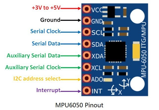
MPU6050 Pinout
The MPU6050 chip consists of 24 pins. But only 8 pins are exposed on the pinout of the module. This MEMS sensor module consists of 8 pins and these pins are used for different configurations and used to read data from the sensor.
- First one is a VCC pin that is used to power the sensor and 3 to 5 volts dc voltages are applied to power on this sensor. But usually, a 5V power source is provided directly from a microcontroller.
- The second [pin is a GND pin which is connected to the source ground and ground pin of a microcontroller.
- Pin number three is a SCL (serial clock) pin which is connected to a microcontroller SCL pin to which we want to interface MPU6050 sensor. SCL is a clock pulse pin used in I2C communication. The clock source is provided by the master device which is a microcontroller in our case.
- Fourth pin is a SDA (serial data) pin which is used to transfer data to a microcontroller. We connect SDA pin of MPU6050 with a SDA pin of a microcontroller
- Fifth one is a XDA (Auxiliary Serial Data) pin which is used to connect external I2C modules with MPU6050 such as magnetometer. But the use of this pin is completely optional.
- Sixth one is a XCL (Auxiliary clock) pin which is also connected to another 12C interface sensor to enable its pin from this sensor module.
- AD0 (Pin7) : AD0 (Address select pin) which is a 12C slave address select pin.For example, if we use more than one MPU6050 modules with a single microcontroller, this pin is used to vary the slave address for each MEMS sensor. By doing so, each MEMS sensor can be easily distinguished on an I2C bus with its unique address.
- INT(Pin8) : The INT (interrupt) pin which is an interrupt digital output pin and used to give indication to a microcontroller that the data is available to read from a MPU6050 sensor module.
The following picture shows the pinout diagram of MPU6050 MEMS module:
MPU6050 Module Circuit Diagram
The following figures show the internal circuit diagram of this module. As you can see that, the hardware used for this module is simple enough to understand. The main part of this module is a MPU6050 IC. Other than this, only a few external resistors, capacitors, a voltage regulator, power source indication LED are used.

The resistors R4 (4.7k) and R5 (4.7k) which are shown in the top right corner in the schematic diagram are the pull-up resistor required for I2C Bus. Pull-up resistors are already connected with SDA and SCL pins of MPU6050 IC. Therefore, we do not need to enable internal pull-up resistors of a microcontroller I2C port. Even if the microcontroller I2C port does not have an internal pull-up resistor, we do not need to use external pull-up resistors.
MPU6050 Sensor Module Working
MPU6050 sensor works on the principle of MEMS (micro electromechanical system) technology. Basically, this sensor module is a six DOF (degree of freedom) or six axis sensor module, therefore, it provides six outputs. From these six outputs values, three come from the gyroscope and three come from the accelerometer. Because both gyroscope and accelerometer are embedded inside a single chip.
As discussed earlier, MPU6050 sensor module provides output data on its I2C pin. Therefore, wew can use a 12C (inter integrated circuit) port of a microcontroller to read sensor output values.
The accelerometer in this chip works on the principle of piezoelectric effect. Suppose a small box with a ball inside it and the walls of this box are made with piezoelectric crystal. When we tilt this box then the ball is forced to move in the direction of inclination due to gravity. When this ball collides with the wall of the box then a small piezo electric current is produced. On the basis of this current we can determine the inclination angle and its magnitude. Similarly, the gyroscope works on the principle of Coriolis acceleration.
Whenever change in motion occurs, an electro-mechanical system of the sensor produces a respective magnitude voltage. A MUP6050 sensor IC also has an interanl 16-bit ADC which measures this voltage change. After that, the sensor stores the voltage value in a FIFO. On every write in the buffer, the interrupt (INT) pin goes high which provides a signal to a microcontroller that the data is ready to read.
How to Interface MPU6050 Module with Microcontroller
As discussed earlier, MPU6050 sensor module provides output data on its I2C pins. Therefore, it is easy to interface this sensor with any microcontroller which has at least one I2C port. A controller such as an Arduino or microcontroller can be used to read data from an MPU6050 sensor module.
Interfacing with Pic Microcontroller
For demonstration and example, we will interface MPU6050 with a pic microcontroller. You can use any pic microcontroller. But in this tutorial, we will use a PIC18F46K22 microcontroller. The interfacing diagram of PIC18F46K22 and MPU6050 is shown below:
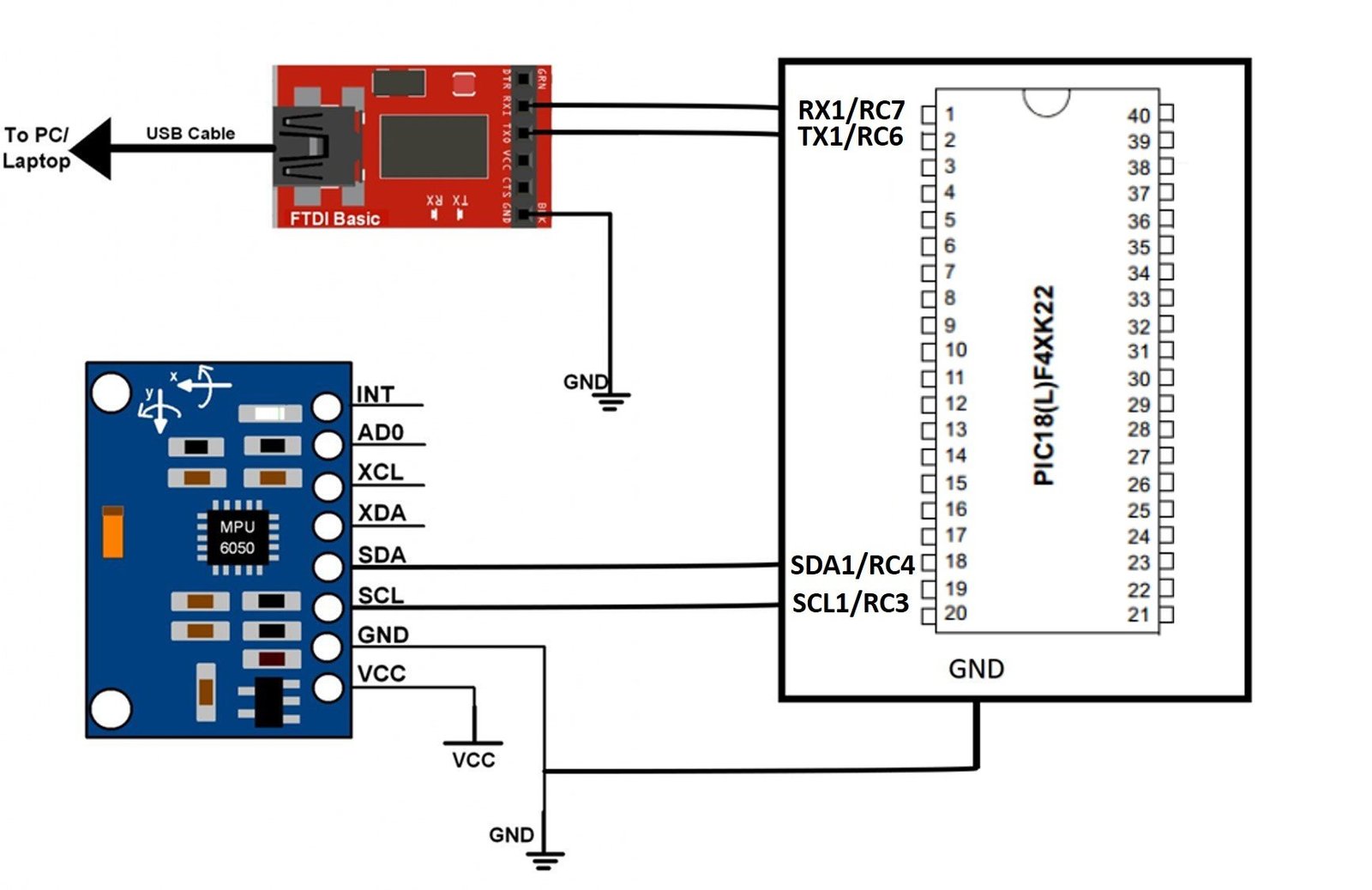
- Connect SDA and SCL pins of a PIC18F46K22 microcontroller with SDA and SCL pins of MPU6050 sensor module, respectively.
- Aslo, connect Vcc and GND pins of a PIC18F46K22 microcontroller with Vcc and GND pins of MPU6050 sensor module, respectively.
I2C communication drivers which we will use in the tutorial was developed in one of our last tutorial on I2C communication with pic microcontroller. You can read it here:
We will use the UART communication module of Pic microcontroller to transfer measured values of gyroscope and accelerometer to the computer. If you don’t know how to use UART communication port of pic microcontroller, you can read this post:
To get sensor data on a computer serial monitor, you need to make connection of pic microcontroller with USB to serial converter cable. If you can check this guide to know how to use an FTDI cable:
Now let’s see the code of MPU6050 for pic microcontroller.
MPU6050 Pic Microcontroller Code (MikroC)
This example code of MPU6050 for PIC18F46K22 microcontroller is written in C language with MikroC for pic compiler.
#define MPU6050_ADDRESS   0xD0
#define MPU6050_RA_XG_OFFS_TC       0x00
#define MPU6050_RA_YG_OFFS_TC       0x01
#define MPU6050_RA_ZG_OFFS_TC       0x02
#define MPU6050_RA_X_FINE_GAIN      0x03
#define MPU6050_RA_Y_FINE_GAIN      0x04
#define MPU6050_RA_Z_FINE_GAIN      0x05
#define MPU6050_RA_XA_OFFS_H        0x06
#define MPU6050_RA_XA_OFFS_L_TC     0x07
#define MPU6050_RA_YA_OFFS_H        0x08
#define MPU6050_RA_YA_OFFS_L_TC     0x09
#define MPU6050_RA_ZA_OFFS_H        0x0A
#define MPU6050_RA_ZA_OFFS_L_TC     0x0B
#define MPU6050_RA_XG_OFFS_USRH     0x13
#define MPU6050_RA_XG_OFFS_USRL     0x14
#define MPU6050_RA_YG_OFFS_USRH     0x15
#define MPU6050_RA_YG_OFFS_USRL     0x16
#define MPU6050_RA_ZG_OFFS_USRH     0x17
#define MPU6050_RA_ZG_OFFS_USRL     0x18
#define MPU6050_RA_SMPLRT_DIV       0x19
#define MPU6050_RA_CONFIG           0x1A
#define MPU6050_RA_GYRO_CONFIG      0x1B
#define MPU6050_RA_ACCEL_CONFIG     0x1C
#define MPU6050_RA_FF_THR           0x1D
#define MPU6050_RA_FF_DUR           0x1E
#define MPU6050_RA_MOT_THR          0x1F
#define MPU6050_RA_MOT_DUR          0x20
#define MPU6050_RA_ZRMOT_THR        0x21
#define MPU6050_RA_ZRMOT_DUR        0x22
#define MPU6050_RA_FIFO_EN          0x23
#define MPU6050_RA_I2C_MST_CTRL     0x24
#define MPU6050_RA_I2C_SLV0_ADDR    0x25
#define MPU6050_RA_I2C_SLV0_REG     0x26
#define MPU6050_RA_I2C_SLV0_CTRL    0x27
#define MPU6050_RA_I2C_SLV1_ADDR    0x28
#define MPU6050_RA_I2C_SLV1_REG     0x29
#define MPU6050_RA_I2C_SLV1_CTRL    0x2A
#define MPU6050_RA_I2C_SLV2_ADDR    0x2B
#define MPU6050_RA_I2C_SLV2_REG     0x2C
#define MPU6050_RA_I2C_SLV2_CTRL    0x2D
#define MPU6050_RA_I2C_SLV3_ADDR    0x2E
#define MPU6050_RA_I2C_SLV3_REG     0x2F
#define MPU6050_RA_I2C_SLV3_CTRL    0x30
#define MPU6050_RA_I2C_SLV4_ADDR    0x31
#define MPU6050_RA_I2C_SLV4_REG     0x32
#define MPU6050_RA_I2C_SLV4_DO      0x33
#define MPU6050_RA_I2C_SLV4_CTRL    0x34
#define MPU6050_RA_I2C_SLV4_DI      0x35
#define MPU6050_RA_I2C_MST_STATUS   0x36
#define MPU6050_RA_INT_PIN_CFG      0x37
#define MPU6050_RA_INT_ENABLE       0x38
#define MPU6050_RA_DMP_INT_STATUS   0x39
#define MPU6050_RA_INT_STATUS       0x3A
#define MPU6050_RA_ACCEL_XOUT_H     0x3B
#define MPU6050_RA_ACCEL_XOUT_L     0x3C
#define MPU6050_RA_ACCEL_YOUT_H     0x3D
#define MPU6050_RA_ACCEL_YOUT_L     0x3E
#define MPU6050_RA_ACCEL_ZOUT_H     0x3F
#define MPU6050_RA_ACCEL_ZOUT_L     0x40
#define MPU6050_RA_TEMP_OUT_H       0x41
#define MPU6050_RA_TEMP_OUT_L       0x42
#define MPU6050_RA_GYRO_XOUT_H      0x43
#define MPU6050_RA_GYRO_XOUT_L      0x44
#define MPU6050_RA_GYRO_YOUT_H      0x45
#define MPU6050_RA_GYRO_YOUT_L      0x46
#define MPU6050_RA_GYRO_ZOUT_H      0x47
#define MPU6050_RA_GYRO_ZOUT_L      0x48
#define MPU6050_RA_EXT_SENS_DATA_00 0x49
#define MPU6050_RA_EXT_SENS_DATA_01 0x4A
#define MPU6050_RA_EXT_SENS_DATA_02 0x4B
#define MPU6050_RA_EXT_SENS_DATA_03 0x4C
#define MPU6050_RA_EXT_SENS_DATA_04 0x4D
#define MPU6050_RA_EXT_SENS_DATA_05 0x4E
#define MPU6050_RA_EXT_SENS_DATA_06 0x4F
#define MPU6050_RA_EXT_SENS_DATA_07 0x50
#define MPU6050_RA_EXT_SENS_DATA_08 0x51
#define MPU6050_RA_EXT_SENS_DATA_09 0x52
#define MPU6050_RA_EXT_SENS_DATA_10 0x53
#define MPU6050_RA_EXT_SENS_DATA_11 0x54
#define MPU6050_RA_EXT_SENS_DATA_12 0x55
#define MPU6050_RA_EXT_SENS_DATA_13 0x56
#define MPU6050_RA_EXT_SENS_DATA_14 0x57
#define MPU6050_RA_EXT_SENS_DATA_15 0x58
#define MPU6050_RA_EXT_SENS_DATA_16 0x59
#define MPU6050_RA_EXT_SENS_DATA_17 0x5A
#define MPU6050_RA_EXT_SENS_DATA_18 0x5B
#define MPU6050_RA_EXT_SENS_DATA_19 0x5C
#define MPU6050_RA_EXT_SENS_DATA_20 0x5D
#define MPU6050_RA_EXT_SENS_DATA_21 0x5E
#define MPU6050_RA_EXT_SENS_DATA_22 0x5F
#define MPU6050_RA_EXT_SENS_DATA_23 0x60
#define MPU6050_RA_MOT_DETECT_STATUS    0x61
#define MPU6050_RA_I2C_SLV0_DO      0x63
#define MPU6050_RA_I2C_SLV1_DO      0x64
#define MPU6050_RA_I2C_SLV2_DO      0x65
#define MPU6050_RA_I2C_SLV3_DO      0x66
#define MPU6050_RA_I2C_MST_DELAY_CTRL   0x67
#define MPU6050_RA_SIGNAL_PATH_RESET    0x68
#define MPU6050_RA_MOT_DETECT_CTRL      0x69
#define MPU6050_RA_USER_CTRL        0x6A
#define MPU6050_RA_PWR_MGMT_1       0x6B
#define MPU6050_RA_PWR_MGMT_2       0x6C
#define MPU6050_RA_BANK_SEL         0x6D
#define MPU6050_RA_MEM_START_ADDR   0x6E
#define MPU6050_RA_MEM_R_W          0x6F
#define MPU6050_RA_DMP_CFG_1        0x70
#define MPU6050_RA_DMP_CFG_2        0x71
#define MPU6050_RA_FIFO_COUNTH      0x72
#define MPU6050_RA_FIFO_COUNTL      0x73
#define MPU6050_RA_FIFO_R_W         0x74
#define MPU6050_RA_WHO_AM_I         0x75


// structures
typedef struct
{
 struct
 {
  signed int X;
  signed int Y;
  signed int Z;
 }Accel;
 signed int Temperatura;
 struct
 {
  signed int X;
  signed int Y;
  signed int Z;
 }Gyro;
}MPU6050;


// I2C functions
void MPU6050_Init()
{
I2C1_Init(400000);
 I2C1_Start();
 I2C1_Wr( MPU6050_ADDRESS );
 I2C1_Wr( MPU6050_RA_PWR_MGMT_1 );
 I2C1_Wr( 2 ); //Sleep OFF
 I2C1_Wr( 0 );
 I2C1_Stop();
 I2C1_Start();
 I2C1_Wr( MPU6050_ADDRESS );
 I2C1_Wr( MPU6050_RA_GYRO_CONFIG );
 I2C1_Wr( 0 ); //gyro_config, +-250 °/s
 I2C1_Wr( 0 ); //accel_config +-2g
 I2C1_Stop();
}

void MPU6050_Read( MPU6050 *Sensor )
{
 I2C1_Start();
 I2C1_Wr( MPU6050_ADDRESS );
 I2C1_Wr( MPU6050_RA_ACCEL_XOUT_H );
 I2C1_Start();
 I2C1_Wr( MPU6050_ADDRESS | 1 );
 Sensor->Accel.X = ( I2C1_Rd(1) << 8 ) | I2C1_Rd(1);
 Sensor->Accel.Y = ( I2C1_Rd(1) << 8 ) | I2C1_Rd(1);
 Sensor->Accel.Z = ( I2C1_Rd(1) << 8 ) | I2C1_Rd(1);
 Sensor->Temperatura = ( I2C1_Rd(1) << 8 ) | I2C1_Rd(1);
 Sensor->Gyro.X = ( I2C1_Rd(1) << 8 ) | I2C1_Rd(1);
 Sensor->Gyro.Y = ( I2C1_Rd(1) << 8 ) | I2C1_Rd(1);
 Sensor->Gyro.Z = ( I2C1_Rd(1) << 8 ) | I2C1_Rd(0);
 I2C1_Stop();
 Sensor->Temperatura += 12421;
 Sensor->Temperatura /= 340;
}

 MPU6050 Sensor;
char msg[12];
void main()
{
     // CMCON = 0x07;
      UART1_init(9600);

      MPU6050_Init();

      while(1)
      {
              MPU6050_Read( &Sensor );

              IntToStr( Sensor.Gyro.X, msg );
               UART1_Write_text(msg);

              IntToStr( Sensor.Gyro.Y, msg );
              UART1_Write_text(msg);

              IntToStr( Sensor.Gyro.Z, msg );
              UART1_Write_text(msg);

                IntToStr( Sensor.Accel.X, msg );
               UART1_Write_text(msg);

              IntToStr( Sensor.Accel.Y, msg );
              UART1_Write_text(msg);

              IntToStr( Sensor.Accel.Z, msg );
              UART1_Write_text(msg);


              Delay_ms( 500 );
      }
}
We have similar guides with other Microcontrollers:
Hi sir Iam trying to interface mpu6050 gyroscope sensor and I used basic code but iam facing compiling error in mpu6050 sensor and I also included mpu library and i2c library also included Arduino library manager but the code was not compiling please tell me how to resolve it thank you sir