There are multiple devices for motion, to do the rotation motion we also have different options. These are DC Motor, Servo Motor, and Stepper Motor. When it comes to high load and rotation by stepwise then we can use the stepper motor. Stepper motor also has multiple types. When we need to use the motor in those smart devices which require a solution for carrying the high load, by using specific torque and load with low voltages then we can use a stepper motor called “NEMA 23”. NEMA 23 comes with 2.3’ Square faceplate.
Recommended Components
The following parts are used in this article, along with a generic electronics kit that is handy for building and testing the circuit.
| Component | How it’s used | Buy on Amazon |
|---|---|---|
| NEMA 23 stepper motor | A NEMA 23 bipolar stepper motor as described in this article. | Check Price |
| Electronic component assortment kit (1390 pcs) | A handy assortment of resistors, capacitors, LEDs, diodes and transistors for building circuits. | Check Price |
| Digital multimeter (AstroAI) | Measures voltage, current, resistance and checks continuity while you build and debug. | Check Price |
| Breadboard | Solderless base for prototyping the circuit. | Check Price |
| Jumper Wires | Make the connections on the breadboard. | Check Price |
As an Amazon Associate we earn from qualifying purchases. Prices and availability are accurate as of the date/time indicated and are subject to change.
Introduction to NEMA 23 stepper motor
It is suitable for 3d printers, CNC Machines, Engraving Machines, and Robot Arms, etc. In low-speed devices which required smart rotatory movement at specific speed without missing any single step can use the NEMA 23. NEMA 23 comes up with 3 Nm torque-speed but it is changeable by applying the different operating speeds. Actually, the torque depends on multiple factors, which are applying current, voltages and third factor is the induction of coil within the motor. The rotation of the motor requires the magnetic field to make a single step. The time required to make the coil fully magnetic depends on the induction of the coil.
Pinout od NEMA 23
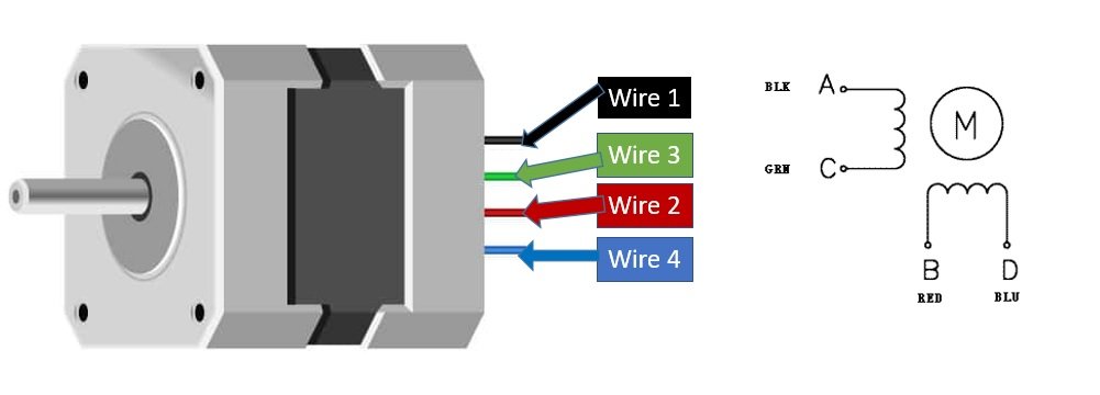
PIN CONFIGURATION of NEMA 23 stepper motor
| PINS | DESCRIPTION | |
|---|---|---|
| Wire 1 | Black | In NEMA 23 all pins are connected internally with the coil. To make the movement we need to magnetize the coil. Internally to control the stepper motor we will have to use the green and black pair. The second pair will be of red and clue. From the wires, the proper functionality can’t describe specifically. It will need a further circuit for proper working. |
| Wire 2 | Red | |
| Wire 3 | Green | |
| Wire 4 | Blue | |
SPECIFICATION of NEMA23
- Its total voltage rating is mostly 3.8V
- Current rating of NEMA 23 is 2.8A
- The Holding torque is equal to 270 oz. in (19 kg-cm).
- One step angle will be a minimum of 1.8 Deg.
- Total steps for each resolution will be 200.
- In NEMA 23 total no of phases is 4
- Total inductance by each phase will be 3.6mH
- The resistance of the coil is 1.3 Ohm per coil.
- Total no of leads in NEMA 23 is 4.
- The size of the motor is 56.4 mm2 x 76 mm. It doesn’t include the shaft.
- The diameter of the motor shaft is 6.35 mm.
The NEMA 23 comes up with 8-10 different models and Power specifications are change for some other models, but the given specification will work all the other models. In some cases, the user has to follow the model specification to make it work properly without any lagging and disruption.
FEATURES of NEMA 23 Stepper motor
- Stepper motor can work like a servo motor by adding encoder and make it operate in a closed-loop.
- It is a small and compactable motor.
- It is digitally set to zero Position.
- It has holding torque up to 19 kg-cm.
- Its resolutions are programmable with PC software.
NEMA 23 Stepper motor datasheet
How to use this stepper motor?
The NEMA 23 looks easy to use but its working principle is a little bit complex for a beginner. It is a bipolar Stepper motor that works exactly like any other bipolar stepper motor. NEMA 23 woks on push and pull system. The internal structure follows the right-hand rule but to rotate it step-wise it has 2 internal coils. The internal coil uses to push the motor from the present location to the next. In the motor, we have 4 wires and 2 coils. A single-coil could make the motor to rotate almost 90 degrees. If one coil is making, the coils to move at 90 degrees than the other coil could prevent it to 45 degrees. This prevention only happens when we keep applying the power at both the coil at the same time.
This could only solve how it works. To make it work for almost 1.8-degree stepwise we need to use the timer method. If we energize both coils in opposite at the same time then we can move the motor stepwise. The problem here is how much time we will require to keep it energized to make a 1.8-degree step. It could easily be done by some motor drivers or controllers but to do it using simple logic we have to make it energize for minimum 2000us. After energizing it stop giving the pulse to the stepper motor. This process may look simple but to make it work perfectly the timer should be precise.
The above method is an internal working method. If we need to control the motor with the stepwise using the controller then we will use a motor driver. The driver will solve the motor power problem and will be able to operate from any controller. The controller will be attached to the motor using a driver. The method to control the motor using a microcontroller will have different logic. All microcontroller uses different libraries but all use the same technique. All microcontroller sends multiple pulses to control the stepper motor. All stepper motor needs a different number of pulses. Some come up will 400 pulses to control the single resolution but NEMA 23 uses 200 pulses to control the 1.8-degree step. By using a microcontroller, we will not just be able to control the steps it could also help us to control the acceleration and speed of the motor. Microcontrollers are smart but sometimes need ICs to control the motor stepwise due to the requirement of the motor.
APPLICATION of NEMA 23 Stepper motor
- It has wide use in CNC Machines.
- Mostly 3d Printer uses NEMA 23 Stepper Motor.
- Some Engraving Machines also use NEMA 23.
- Low Power Laser Cutter also use this stepper motor.
- Hard drives also come up with Stepper Motor NEMA 23.
- Automatic Pick and Place machines use NEMA 23 due to its load-carrying efficiency and ability
- NEMA 32 also uses in Linear Actuators.
- Due to its step precision, it also uses is Precise cutting Machine.
Example with Arduino
There are multiple drivers for different stepper motors due to their Power rating. TB6600 and TB6560 are the two famous ones. We can use anyone from them to control the NEMA 23. Here we will describe the motor movement method with TB6560.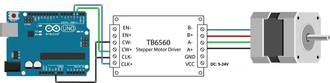
Connect the NEMA 23 with TB6560 as seen in the below diagram. The Power supply attaches to the TB6550 will be 5-24V and 2.8A – 3A. The module could handle the current of about 3.5A. The motor could get burn in case of a higher current. So, keep it between 2.8A – 3A. The module also comes up with some internal protection like overheating, low voltage shutdown and overcurrent. The in-circuit diagram, you may notice that Enable pins are disconnected. It means that enable pins will be always low and drivers will always be in a working state.
In this example, we are connecting drivers with the motor as a common cathode. All negative is common and positive will be used to control the direction and resolution. Pin 2 of Arduino will be connected to CW+ which will be used to control the direction of the motor, and Pin 3 connected to CLK+ which will be used to give the HIGH pulse so the motor could rotate when pulse will generate. The following actions will happen when Arduino will send the pulses.
- If Pin 2 is HIGH motor will rotate clockwise, otherwise anti-clockwise
- A single HIGH-LOW pulse with a delay of a minimum 2000 microsecond will produce a single step of 1.8 degrees of the stepper motor. The decrease in delay will make the move fast.
- Total 200 HIGH-LOW pulse will be required to generate a single rotation of the motor.
- In a closed-loop of Arduino motor could be used as a servo motor but like servo motor, It will be unable to generate feedback to the controller.
The following Arduino code will be used to generate a single step:
void setup() {

pinMode(2,OUTPUT);

pinMode(3,OUTPUT);

}

void loop() {

// USE this for CLOCK WISE

// digitalWrite(2,HIGH);

// USE this for ANTI-CLOCK WISE

// digitalWrite(2,LOW);

digitalWrite(3, HIGH);

delayMicroseconds(2000);

digitalWrite(3, LOW);

delayMicroseconds(2000);

// change the delays for change in speed

}
By using the driver, the controlling of Stepper Motor becomes Easy. The above code is simple but there are also multiple libraries that could control the stepper motor just by a single command. The using of the stepper motor is easy for anyone. It becomes simple and easy just like any other DC Motor. You may like to check other related articles:
can decrease the stepping angle from 1.8 degree to 0.5 degree by using any other stepper driver/controller