In a world where alternative energy solutions are gaining increasing popularity, the demand for efficient and reliable power inverters is on the rise. Among the various types of inverters available in the market, pure sine wave inverters have emerged as a preferred choice for their ability to deliver high-quality, stable electrical output. Whether it’s for powering sensitive electronic devices, solar energy systems, or grid tie applications, pure sine wave inverters offer numerous advantages.
In this article, we will explore the different methods employed in the manufacturing of pure sine wave inverters, with a particular focus on the switch mode power supply (SMPS) method and the more traditional or common method. We will delve into the block diagram, circuit components, and operational principles of both approaches, shedding light on their advantages and considerations to keep in mind during the design and implementation process. Join us on this informative journey as we unravel the intricacies of pure sine wave inverters and empower you with invaluable knowledge for your own projects.
- Pure sine wave Inverter using pic microcontroller, power inverter, solar inverter and grid tie inverter are manufacture now a days in two ways:
- Switch mode power supply method
- Common method or old method
Introduction
A pure sine wave inverter is an electronic device that converts direct current (DC) electricity, typically from a battery or a solar panel, into alternating current (AC) electricity with a waveform that closely resembles a pure sine wave. A pure sine wave is a smooth, continuous waveform that replicates the type of electricity you get from the electrical grid.
Characteristics
Key characteristics of a pure sine wave inverter:
Clean and Smooth Output: A pure sine wave inverter generates a clean and smooth AC output waveform, which is nearly identical to the type of electricity supplied by utility companies. This makes it suitable for running a wide range of electrical and electronic devices.
Compatibility: Pure sine wave power is suitable for sensitive electronics and appliances, including computers, audio and video equipment, medical devices, and more. Many modern appliances and gadgets function optimally with pure sine wave power.
High Efficiency: These inverters are designed for high efficiency, which means that they convert a large portion of the DC power into AC power, minimizing energy loss during the conversion process.
Low Harmonic Distortion: Pure sine wave inverters typically produce low harmonic distortion in their output waveform, which is essential for the proper functioning of many devices.
Versatility: Pure sine wave inverters are versatile and can be used in a variety of applications, such as in off-grid solar power systems, RVs, boats, and backup power solutions for homes and businesses.
Reliability: They are known for their reliability and are often used in critical applications where a stable and high-quality power supply is essential.
In contrast, modified sine wave or square wave inverters generate AC waveforms that are not as clean and can introduce electrical noise, which can affect the performance and lifespan of certain devices.
Pure sine wave inverters are commonly used in situations where the quality of the power supply is critical, ensuring that sensitive equipment operates efficiently and reliably.
Block Diagram
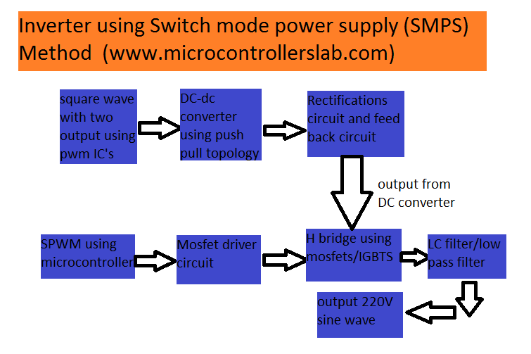
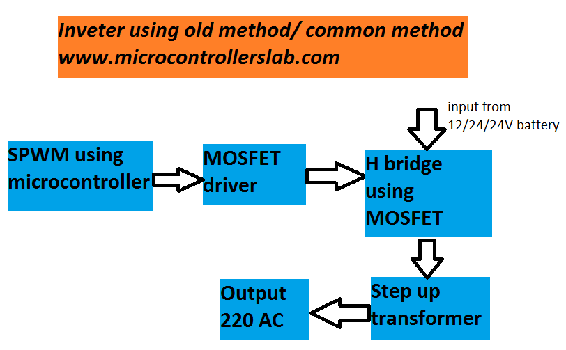
The following two figures show block diagram of two different types of pure sine wave inverters.
SMPS Type
In the above diagrams, both methods are used in inverters. However, the SMPS method is used in the latest pure sine wave inverter. This is because switch mode power supplies are more efficient than the old method. The SMPS method has high efficiency, low harmonic distortion, and low standby losses. I will also discuss the SMPS method in these tutorials on pure sine wave inverters.
Iron Core Transformer Type
In the first diagram, two square wave outputs are used to drive MOSFETs of a push-pull converter. If you are generating square waves with a microcontroller, then you have to use a MOSFET driver like IR2210 to drive the push-pull converter MOSFETs. Alternatively, you can also use PWM controller ICs to generate the two square waves. The advantage of using PWM controller ICs is that you don’t have to use a MOSFET driver. SG3525 PWM controller ICs have a built-in MOSFET driver using a totem pole. Another advantage is that one can easily implement feedback through these ICs. I will explain the use of SG3525 in the next tutorial.
MOSFETs Selection
Selection of MOSFETs depends on the power rating of your inverter design. Commonly, IRF3205 is used in most inverters. Push-pull topology is used due to its high power handling capability. We want to step up the DC voltage from 12/24 volts to 311 volts (peak of sine wave voltage). A chopper or high-frequency transformer is used to step up the DC voltage. A rectifier is then used to convert the voltage into pure DC after the chopper. The selection of diodes for the rectifier circuit also depends on the power rating of the power inverter. One should check the maximum forward current and voltage capability of the diodes. It is better to use an LC filter after the rectifier circuit. However, if you use a capacitor of 400V, it will also work fine.
Role of H-Bridge
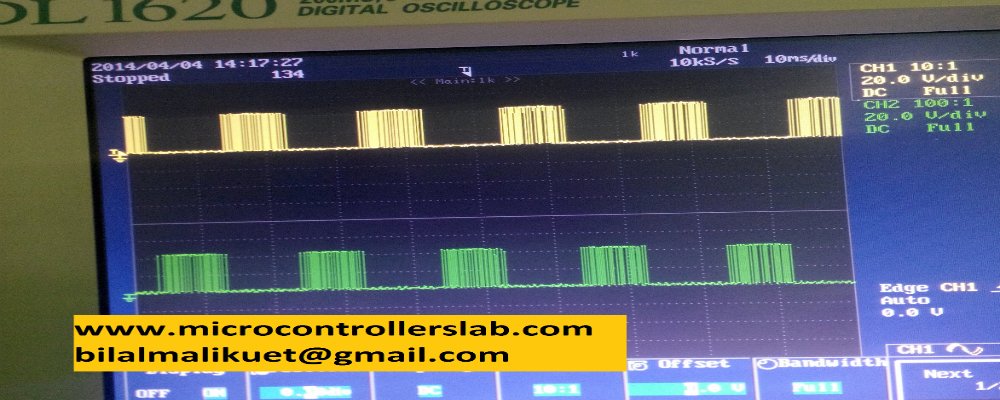
After rectifying the voltage, we feed a 311-volt output from the DC/DC converter to the H bridge. The H bridge generates the positive and negative cycles of AC voltage. We use IRF840 in our final year project “Hybrid Pure Sine Wave Inverter”. The IRF840 performs well when we use proper heat sinks with them. We use the Sinusoidal Pulse Width Modulation (SPWM) technique to generate a pure sine wave output from the inverter. We use the PIC16F877A microcontroller to generate SPWM. Then, feed these SPWM waves to the MOSFETs of the H bridge. We operate the H bridge MOSFETs in such a way that we obtain a pulsating output from the H bridge’s output. The diagram below shows the generated SPWM:
Output of H bridge is fed to an LC filter to remove harmonics from the output. A neat and clean sine wave output can be obtained by using a proper LC filter. I have just tried to give you a brief overview of a pure sine wave inverter or the SMPS method pure sine wave inverter. Before making a pure sine wave inverter, one should keep these things in mind:
- Power electronics circuits are very complicated.
- You may have to make your circuits again and again to find issues.
- Components selection is very critical like MOSFETS, MOSFET drivers and LC Filter values selection
I have written complete articles on each block of SMPS-based pure sine wave inverter. Click on the following articles to learn about their use and ways to diagnose problems in these circuits.
- PWM controllers IC SG3525: Use and Application
- How to Use MOSFET DRIVER 1R2110
- DC-DC Converter Using Push-Pull Topology
- How to Make an H Bridge and Diagnose Problems
- SPWM Generation Using PIC16F877A Microcontroller
- Complete Circuit Diagram of Pure Sine Wave Inverter and Coding
Conclusion
In pure sine wave inverters have become a popular choice for numerous applications due to their ability to provide high-quality and stable electrical output. This article has delved into the manufacturing methods of pure sine wave inverters, with a particular focus on the switch mode power supply (SMPS) method and the more traditional or common method. The advantages and considerations of each approach have been discussed, shedding light on their operational principles and circuit components. By exploring the intricacies of pure sine wave inverters, we hope to empower readers with invaluable knowledge for their own projects. For more in-depth information, the provided links to related articles will serve as helpful resources.
hey brother it is very interesting to read your articles …..you said that in push pull topology it is better to use LC filter after rectifier or we can use capacitor of value 400v…….
i just to want to know the values for L and C……and if i will use capacitor then which of the capacitor you are talking about……..is this capacitor you already used in the push pull topology……..
and what if i don’t use LC filter or any capacitor……….
id: aalfeen_shahbaz@yahoo.com
thanks for your compliments 🙂
yeah either you can use polar capacitor of 400 volt . You can also use LC filter. L values , you can use around 5mH and yes the same capacitor which I have used already in circuit diagram.
for LC filter you mean C5 capacitor (220uF)…………?
am i right……….?
an d if i wanna use 400v capacitor then what would be its capacitance……….?
an d if i wanna use 400v capacitor then what would be its capacitance……….?
for LC filter you mean C5 capacitor (220uF)…………?
am i right……….?
That’s very
Bilal can you share me your complete Schematic of inverter with componet values and complete coding
my email id is naveedijaz_alex@yahoo.com
Bilal malik..
you are owsum.. I want to meet you.. its really interesting ..
mubshir_88@hotmail.com
regards Malik Muhammad
For what purpose you want to meet me ?
Awla work bhai…..Allah apko kamyab kren……
Nice work brother
thanks
please sir let us see the circuit diagram of the LC filter. i need the circuit for proper connection. 2.2uf, 5mH right? please give us the circuit. thanks
Thanks for your good instruction.
Bilal can you share me your complete Schematic of inverter with componet values and complete coding
my email id is trandangsinh@gmail.com
Bilal, pls share your complete circuit diagram with me sir.
Its quite a good Job you have done.
My mail is abiola.sunday@gmail.com
pls, i need a complete circuit diagram of pure sine wave including the IGBT gate driver. thanks. this is my e-mail. samshogelectro2011@yahoo.com
code is not for free
I have a grid tie inverter 1000w there are 13 mosfet transistors on DC side
one transistor is shortcut-ed and bad and more if them seems to be bad also
the mosfet transistors don´t have a name no model number nothing
I don´t know what to replace them with
Can i replace them with Mosfet IRF3205 does anybody know ?
Commonly Mosfet IRF3205 is used in most of inveters it say here
the inverter has 20-50 volt dc input and 230 volt ac output
it is a chines GTI 1000watt type inverter
Can i have the matlab simulation design for the above smps inverter…please
how much is the code with explanation
50$
sir ,
I have a doubt
can i give 12V dc instead of 310V dc for the same circuit that you have explained above .
will it work ?
will it give 12vAC as the inverter output?
do i need to change mosfet
Hello bro nice work
please i need the code for this project
here is my email contact me so we can discuss
Thanks.
Hello Bilal, I want to get the code and your explanation greetings
Hi Balal, I have been trying to contact you on email.
Hello Sir,
I want to know how much this project cost you?
please! help me a code use pic16f877a driver push-pull 12VDC-400VDC power 1kw
pls, i need complete circuit diagram of charge pump of 220v ac to 12v dc at 100ah
Do you sell these designs and programming or complete modules?
Im interested in Variable Frequency output Solar inverters in
a)1.2kw 200vdc to 120VAC single phase
b) 5kW 350vdc input to 220VAC single phase output
I also need the LC filter circuit diagram…..please