In this STM32 Blue Pill tutorial, we will learn how to configure and handle external interrupts using HAL Library in STM32Cube IDE. We will demonstrate this through an example with a push button and an LED. Additionally, we will also show you how to measure Blue Pill interrupt latency via an oscilloscope measurement.
By the end of this article you will be able to know about:
- External Interrupts in Blue Pill STM32
- Configure GPIO Output Pin & Input Pin using STM32Cube IDE
- Set the Input Pin as an interrupt pin (rising edge)
- Toggle LED (output pin) on each rising edge
- Measure Interrupt Latency
In the last two tutorials, we have learned to use GPIO pins of STM32 Blue Pill as digital input and output pins:
- STM32 Blue Pill GPIO Pins with STM32Cube IDE: LED Blinking Tutorial
- Push Button with STM32 Blue Pill using STM32Cube IDE – Read Digital Input Pins
Interrupts Introduction
Interrupts are used to handle events that do not happen during the sequential execution of a program. For example, we want to perform certain tasks and these tasks execute sequentially in your program. But there are few tasks that only execute when a special event occurs such as an external trigger signal to the digital input pin of a microcontroller.
An external interrupt or a ‘hardware interrupt’ is caused by the external hardware module. For example, there is a Touch Interrupt which happens when touch is detected and a GPIO interrupt when a key is pressed down. In this tutorial, we will focus on this type of interrupt.
Working Process
With interrupt, we do not need to continuously check the state of the digital input pin. When an interrupt occurs (a change is detected), the processor stops the execution of the main program and a function is called upon known as ISR or the Interrupt Service Routine. The processor then temporarily works on a different task (ISR) and then gets back to the main program after the handling routine has ended.
This is shown in the figure below.
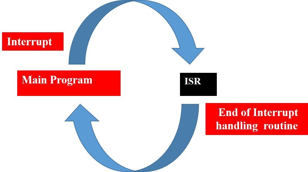
An example can be that of pressing a push button or motion detection with a PIR Sensor. In both cases, a push button or a PIR motion sensor can be used to trigger an interrupt. Therefore, when an external event occurs, the processor stops what it is doing and executes the interrupt service routine which we define for the respective event. After that, it returns to the current program. External Interrupts are extremely useful because with their help we do not have to constantly monitor the digital input pin state.
ARM cortex Interrupts
The STM32 ARM microcontroller interrupts are generated in the following manner:
The system runs the ISR and then goes back to the main program. The NVIC and EXTI are configured. The Interrupt Service Routine (ISR) also known as the interrupt service routine handler is defined to enable the external interrupts.
Let us learn about the important features which are needed to configure external interrupts in STM32 microcontrollers
Interrupt Lines (EXTI0-EXTI15)
The STM32 ARM microcontroller features 23 event sources which are divided into two sections. The first section corresponds t external pins on each port which are P0-P15. The second section corresponds to RTC, ethernet, USB interrupts. Therefore, in the first section, we have 16 lines corresponding to line0 till line15. All of these map to a pin number.
The diagram below shows how the GPIO pins are connected to the 16 interrupt lines:
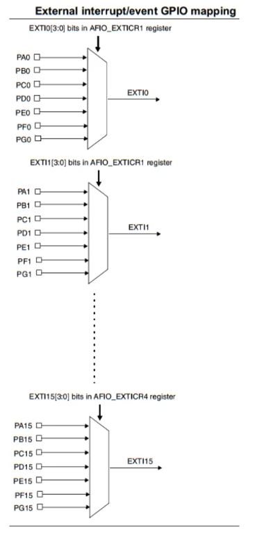
One important thing to note here is that same number pins are connected to line with the same number. All of these then join to form a single line. Additionally, we can not use two pins one one line at the same time. For example out of PA1, PB1, PC1, PD1, PE1, PF1 and PG1 you can only use a single pin out of all these. This is because they are all connected to the same line EXTI1. However you can use PA1 and PA2 at the same time as they are connected with different lines.
Now each of these lines EXTI0-EXTI15 can be used to trigger an interrupt on different modes of the signal : rising edge, falling edge or rising_falling edge.
Interrupt Handler (ISR)
The next important feature is the ISR or the interrupt handler. In order to handle the interrupts we use the ISR function.
The table below shows the different interrupt handlers for the GPIO pins:
| GPIO Pin | IRQ | Handler | Description |
| 0 | EXTI0_IRQn | void EXTI0_IRQHandler() | Handler for pins connected to line 0 |
| 1 | EXTI1_IRQn | void EXTI1_IRQHandler() | Handler for pins connected to line 1 |
| 2 | EXTI2_IRQn | void EXTI2_IRQHandler() | Handler for pins connected to line 2 |
| 3 | EXTI3_IRQn | void EXTI3_IRQHandler() | Handler for pins connected to line 3 |
| 4 | EXTI4_IRQn | void EXTI4_IRQHandler() | Handler for pins connected to line 4 |
| 5 | EXTI9_5_IRQn | void EXTI9_5_IRQHandler() | Handler for pins connected to line 5 |
| 6 | EXTI9_5_IRQn | void EXTI9_5_IRQHandler() | Handler for pins connected to line 6 |
| 7 | EXTI9_5_IRQn | void EXTI9_5_IRQHandler() | Handler for pins connected to line 7 |
| 8 | EXTI9_5_IRQn | void EXTI9_5_IRQHandler() | Handler for pins connected to line 8 |
| 9 | EXTI9_5_IRQn | void EXTI9_5_IRQHandler() | Handler for pins connected to line 9 |
| 10 | EXTI15_10_IRQn | void EXTI15_10_IRQHandler() | Handler for pins connected to line 10 |
| 11 | EXTI15_10_IRQn | void EXTI15_10_IRQHandler() | Handler for pins connected to line 11 |
| 12 | EXTI15_10_IRQn | void EXTI15_10_IRQHandler() | Handler for pins connected to line 12 |
| 13 | EXTI15_10_IRQn | void EXTI15_10_IRQHandler() | Handler for pins connected to line 13 |
| 14 | EXTI15_10_IRQn | void EXTI15_10_IRQHandler() | Handler for pins connected to line 14 |
| 15 | EXTI15_10_IRQn | void EXTI15_10_IRQHandler() | Handler for pins connected to line 15 |
We have a total of seven interrupt handlers according to the pin which we will set up as the external interrupt pin. This is because Line5-Line9 and Line10-Line15 have the same interrupt handler.
The IRQ has to be set for NVIC and the handler shows the prototype of the handler function.
External Interrupt using a Push Button to toggle LED
Now we will learn how to handle interrupts in the Blue Pill STM32 using a push button to toggle an LED. The push button will be connected to an interrupt pin of STM32 and configured as an input. Whereas the LED will be set up as a digital output. The LED will be toggled on each rising edge.
The following components are required:
- Blue Pill STM32 board
- One Push button
- One 5mm LED
- One 220 ohm resistor
- One 10k ohm resistor
- Breadboard
- Connecting Wires
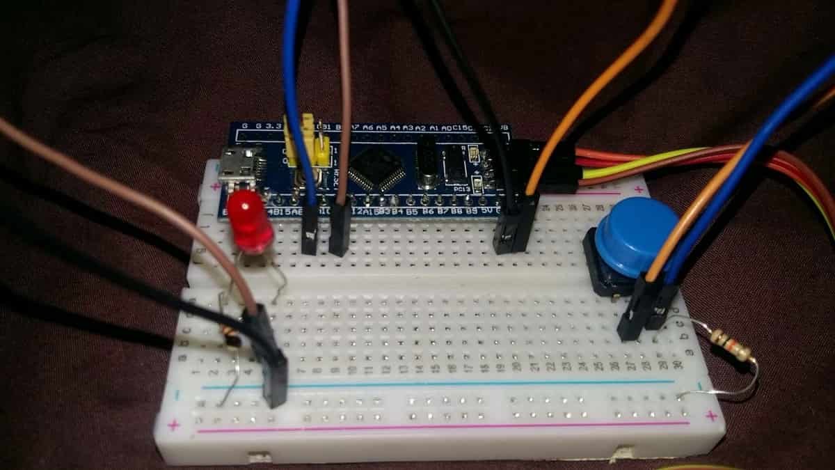
Assemble your circuit as shown below:
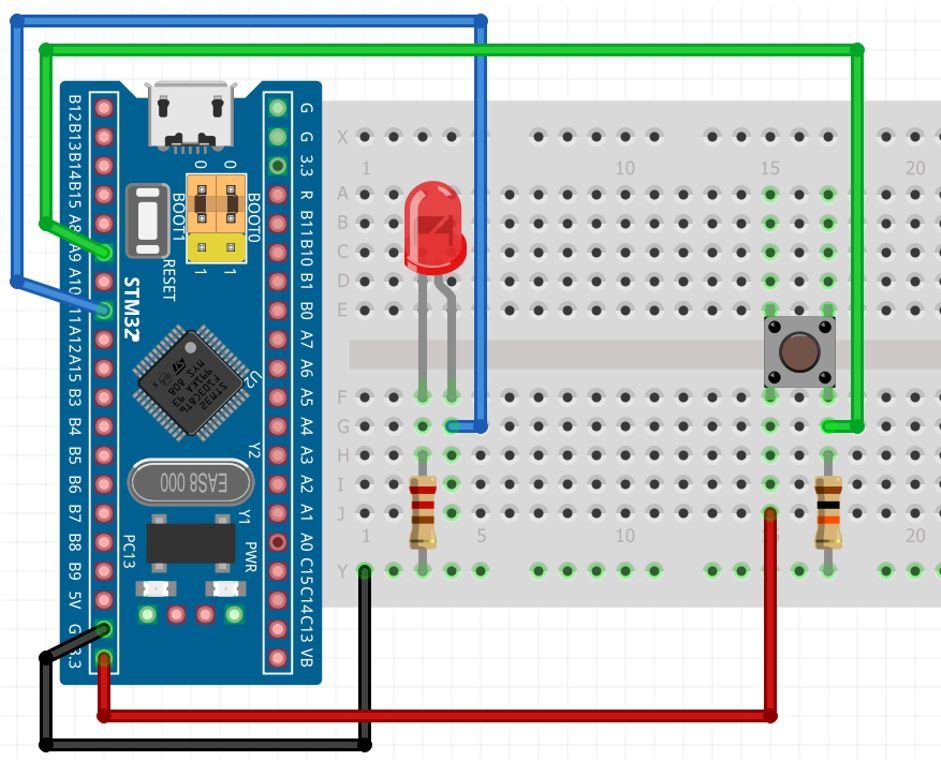
In the above diagram, we can see that pin A11 is connected with the anode pin of LED, and the cathode pin is connected with the common ground through the 220-ohm resistor.
The push button has four terminals. One terminal is powered by 3.3 volts from STM32 and the other terminal is connected by Pin A9 and the 10k ohm resistor which acts as a pull-down resistor. The other end of the resistor is connected with the common ground.
When the pushbutton is not pressed, logic low will appear on A9, or push button state will be low and when the push button is pressed, a logic high will be on A9. That means a rising edge occurs when a push button is pressed. We can detect this rising edge with the help of interrupt pins of STM32. You can use any appropriate Blue Pill STM32 interrupt pin to connect with the push button.
Program External Interrupts with STM32 Blue Pill in STM32Cube IDE
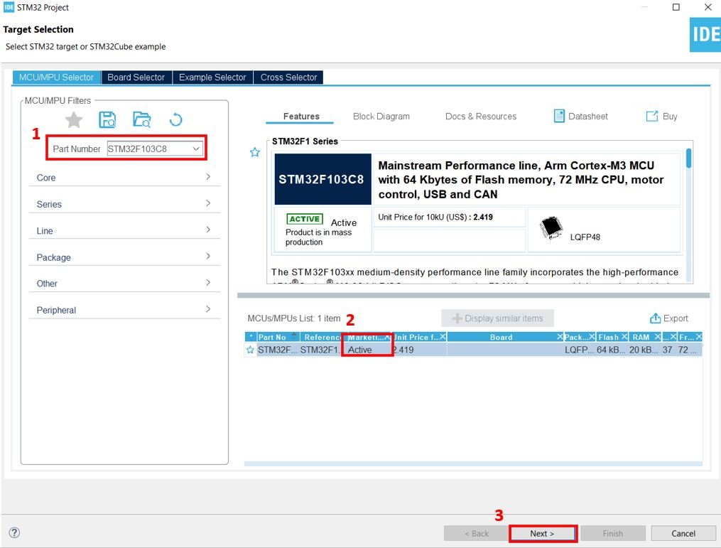
We will use STM32Cube IDE to program our STM32 board. Open the IDE and head over to a new project.
Then for the target selection, specify the STM32 Blue Pill board number. After that click at the column as shown in the picture below. Then click the ‘Next’ button.
The following window will open. Here specify the name of your project then click ‘Finish’ to complete the setup of your project.

Device Configuration Tool
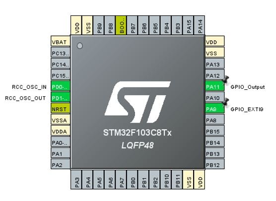
The Device Configuration Tool will now open. Here we will configure the external interrupt input pin and the output pin. For the input pin we have chosen the digital pin PA9 and for the output pin we have chosen the digital pin PA11.
PA9 in our case is connected with the push button and PA11 is connected with the LED as mentioned before.
First, click at PA 11 and set it as GPIO_Output.
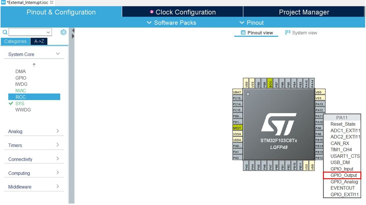
Then click PA9 and set it as GPIO_EXTI9.

This is how the two pins will look like after attaching them with specific modes.

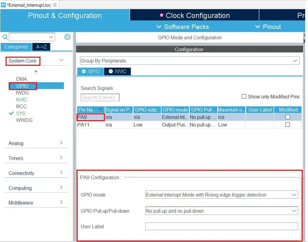
No go to System Core > GPIO and click PA9. Below you will be able to view its configuration.
Here you can see that the GPIO mode is selected as “External Interrupt with Rising edge trigger detection.” You can change it according to your preference from a choice of different triggers for the external interrupt. In our case we want the external interrupt to trigger on a rising edge.
Additionally, we have used a no-pull GPIO configuration as we will be using a physical pull down resistor connected with the push button. You even have an option to add a label to this pin. We have not used any label.
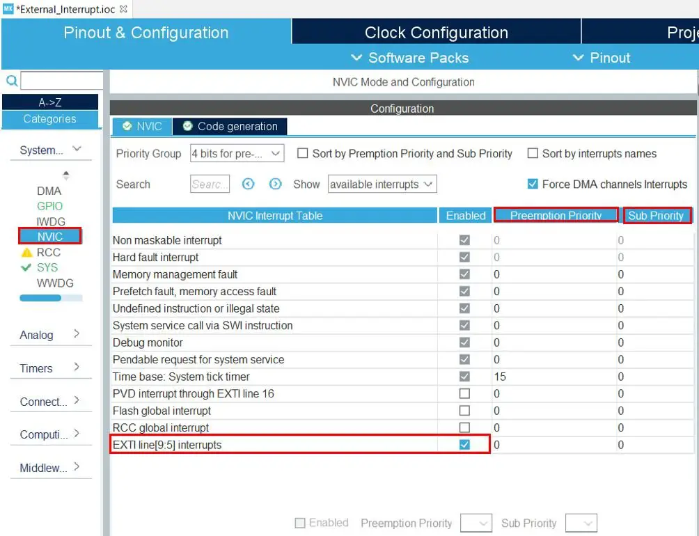
Now click NVIC and enable the interrupt for EXTI line 9 as shown below.

You even have the option to set the priority of the NVIC interrupt. Head over to System Core > NVIC. Here you will be able to set the priority for EXTI line 9 interrupt. We have left it as default.
Now go to System Core > RCC then select ‘Crystal/Ceramic Resonator’ in from the High Speed Clock feature.
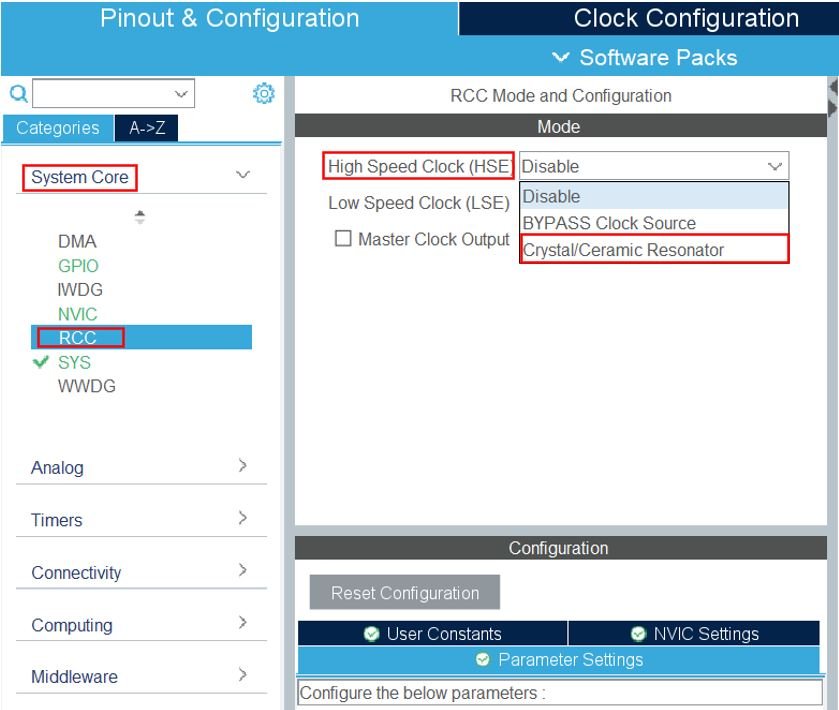
Now we have enabled the RCC external clock source.
Clock Configuration
Next go to the Clock Configuration found at the top. This will open the following window. Here we will select the clock frequency.
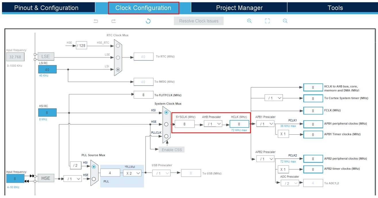
You can specify your system clock. We will set it as 72 MHz. These are the configurations we have set:

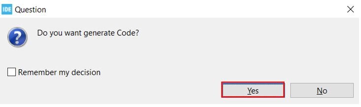
Now we will save our file. Press Ctrl + S. The following window will appear. Click ‘Yes.’ This will generate a template code for you.
Another window will appear that will ask if you want to open the perspective. Click ‘Yes.’

External Interrupts with STM32 Blue Pill Code
Now the following page opens. On the right side you will be able to view the Outline of the code. This happened because we opened our code with perspective. In the centre you can view the main.c file and on the left you can view the Project Explorer. If you want to go to the Device Configuration Tool, then click the PushButton.ioc tab.

Now let us look at our main.c file that was generated. Look for the MX_GPIO_Init() function.
static void MX_GPIO_Init(void)
{
  GPIO_InitTypeDef GPIO_InitStruct = {0};

  /* GPIO Ports Clock Enable */
  __HAL_RCC_GPIOD_CLK_ENABLE();
  __HAL_RCC_GPIOA_CLK_ENABLE();

  /*Configure GPIO pin Output Level */
  HAL_GPIO_WritePin(GPIOA, GPIO_PIN_11, GPIO_PIN_RESET);

  /*Configure GPIO pin : PA9 */
  GPIO_InitStruct.Pin = GPIO_PIN_9;
  GPIO_InitStruct.Mode = GPIO_MODE_IT_RISING;
  GPIO_InitStruct.Pull = GPIO_NOPULL;
  HAL_GPIO_Init(GPIOA, &GPIO_InitStruct);

  /*Configure GPIO pin : PA11 */
  GPIO_InitStruct.Pin = GPIO_PIN_11;
  GPIO_InitStruct.Mode = GPIO_MODE_OUTPUT_PP;
  GPIO_InitStruct.Pull = GPIO_NOPULL;
  GPIO_InitStruct.Speed = GPIO_SPEED_FREQ_LOW;
  HAL_GPIO_Init(GPIOA, &GPIO_InitStruct);

  /* EXTI interrupt init*/
  HAL_NVIC_SetPriority(EXTI9_5_IRQn, 0, 0);
  HAL_NVIC_EnableIRQ(EXTI9_5_IRQn);

}
This is the function that initializes the GPIO pins that we have set up in the Device Configuration Tool. Here as you can see Pin A9 is configured as an external interrupt rising edge input with no pull. This means that the pin A9 is setup in high impedance.
Moreover, Pin A11 is configured as an output with no pull as well. The set up speed is set to low frequency.
Then for both the pins the HAL_GPIO_Init() function is also called. This function takes in two parameters. The first parameter is the GPIO Port which is GPIOA in our case. The second parameter is &GPIO_InitStruct.
External Interrupt
The external interrupt is initialized in the following lines:
  /* EXTI interrupt init*/
  HAL_NVIC_SetPriority(EXTI9_5_IRQn, 0, 0);
  HAL_NVIC_EnableIRQ(EXTI9_5_IRQn);
Here we are first setting the priority of the EXTI line 9 interrupt and then enabling the IRQ. We had already set the mode of the interrupt to rising edge trigger while configuring the input pin.
ISR
The interrupt channel is enabled. After that let us look at how the handler is implemented. You can view the ISR generated in the stm32f1xx_it.h file.
void EXTI9_5_IRQHandler(void)
{
  HAL_GPIO_EXTI_IRQHandler(GPIO_PIN_9);
}
The void EXTI9_5_IRQHandler(void) function is the ISR that gets called whenever the external interrupt is triggered. As we saw in the table previously, EXTI9_5_IRQHandler handles interrupts from more than one pin. In our case we are using a single external interrupt pin 9 therefore we called the HAL_GPIO_EXTI_IRQHandler() with the GPIO pin as the parameter inside it once. If we had multiple external interrupt pins enabled e.g. pin 7 or pin 8 then we would have called each GPIO handler inside this function.
Remember: For pin 0 to 4 interrupts, there is only one GPIO handler to call.
Modifying Code
Inside the main.c file, after the main() function insert this HAL_GPIO_EXTI_Callback() function. This is the external interrupt ISR handler callback function which is responsible to check the interrupt pin source, then toggle the output GPIO pin accordingly.
// External Interrupt ISR Handler CallBackFun
void HAL_GPIO_EXTI_Callback(uint16_t GPIO_Pin)
{
    if(GPIO_Pin == GPIO_PIN_9) // INT Source is pin A9
    {
    HAL_GPIO_TogglePin(GPIOA, GPIO_PIN_11); // Toggle LED
    }
}
One thing to notice here is that only the pin number is being accessed by the callback function. Therefore we can configure interrupts on all 16 different pins regardless of the GPIO number.
To conclude we can set up an interrupt on PA1 and PB4, but we can not set up simultaneous interrupts on PA1 and PB1.
main.c file
/* USER CODE BEGIN Header */
/**
  ******************************************************************************
  * @file           : main.c
  * @brief          : Main program body
  ******************************************************************************
  * @attention
  *
  * Copyright (c) 2021 STMicroelectronics.
  * All rights reserved.
  *
  * This software is licensed under terms that can be found in the LICENSE file
  * in the root directory of this software component.
  * If no LICENSE file comes with this software, it is provided AS-IS.
  *
  ******************************************************************************
  */
/* USER CODE END Header */
/* Includes ------------------------------------------------------------------*/
#include "main.h"

void SystemClock_Config(void);
static void MX_GPIO_Init(void);

int main(void)
{
  HAL_Init();

  SystemClock_Config();

  MX_GPIO_Init();

  while (1)
  {

  }

}

// External Interrupt ISR Handler CallBackFun
void HAL_GPIO_EXTI_Callback(uint16_t GPIO_Pin)
{
    if(GPIO_Pin == GPIO_PIN_9) // INT Source is pin A9
    {
    HAL_GPIO_TogglePin(GPIOA, GPIO_PIN_11); // Toggle LED
    }
}

void SystemClock_Config(void)
{
  RCC_OscInitTypeDef RCC_OscInitStruct = {0};
  RCC_ClkInitTypeDef RCC_ClkInitStruct = {0};

  /** Initializes the RCC Oscillators according to the specified parameters
  * in the RCC_OscInitTypeDef structure.
  */
  RCC_OscInitStruct.OscillatorType = RCC_OSCILLATORTYPE_HSE;
  RCC_OscInitStruct.HSEState = RCC_HSE_ON;
  RCC_OscInitStruct.HSEPredivValue = RCC_HSE_PREDIV_DIV1;
  RCC_OscInitStruct.HSIState = RCC_HSI_ON;
  RCC_OscInitStruct.PLL.PLLState = RCC_PLL_ON;
  RCC_OscInitStruct.PLL.PLLSource = RCC_PLLSOURCE_HSE;
  RCC_OscInitStruct.PLL.PLLMUL = RCC_PLL_MUL9;
  if (HAL_RCC_OscConfig(&RCC_OscInitStruct) != HAL_OK)
  {
    Error_Handler();
  }
  /** Initializes the CPU, AHB and APB buses clocks
  */
  RCC_ClkInitStruct.ClockType = RCC_CLOCKTYPE_HCLK|RCC_CLOCKTYPE_SYSCLK
                              |RCC_CLOCKTYPE_PCLK1|RCC_CLOCKTYPE_PCLK2;
  RCC_ClkInitStruct.SYSCLKSource = RCC_SYSCLKSOURCE_PLLCLK;
  RCC_ClkInitStruct.AHBCLKDivider = RCC_SYSCLK_DIV1;
  RCC_ClkInitStruct.APB1CLKDivider = RCC_HCLK_DIV2;
  RCC_ClkInitStruct.APB2CLKDivider = RCC_HCLK_DIV1;

  if (HAL_RCC_ClockConfig(&RCC_ClkInitStruct, FLASH_LATENCY_2) != HAL_OK)
  {
    Error_Handler();
  }
}


static void MX_GPIO_Init(void)
{
  GPIO_InitTypeDef GPIO_InitStruct = {0};

  /* GPIO Ports Clock Enable */
  __HAL_RCC_GPIOD_CLK_ENABLE();
  __HAL_RCC_GPIOA_CLK_ENABLE();

  /*Configure GPIO pin Output Level */
  HAL_GPIO_WritePin(GPIOA, GPIO_PIN_11, GPIO_PIN_RESET);

  /*Configure GPIO pin : PA9 */
  GPIO_InitStruct.Pin = GPIO_PIN_9;
  GPIO_InitStruct.Mode = GPIO_MODE_IT_RISING;
  GPIO_InitStruct.Pull = GPIO_NOPULL;
  HAL_GPIO_Init(GPIOA, &GPIO_InitStruct);

  /*Configure GPIO pin : PA11 */
  GPIO_InitStruct.Pin = GPIO_PIN_11;
  GPIO_InitStruct.Mode = GPIO_MODE_OUTPUT_PP;
  GPIO_InitStruct.Pull = GPIO_NOPULL;
  GPIO_InitStruct.Speed = GPIO_SPEED_FREQ_LOW;
  HAL_GPIO_Init(GPIOA, &GPIO_InitStruct);

  /* EXTI interrupt init*/
  HAL_NVIC_SetPriority(EXTI9_5_IRQn, 0, 0);
  HAL_NVIC_EnableIRQ(EXTI9_5_IRQn);

}


void Error_Handler(void)
{
  /* USER CODE BEGIN Error_Handler_Debug */
  /* User can add his own implementation to report the HAL error return state */
  __disable_irq();
  while (1)
  {
  }
  /* USER CODE END Error_Handler_Debug */
}

#ifdef  USE_FULL_ASSERT
/**
  * @brief  Reports the name of the source file and the source line number
  *         where the assert_param error has occurred.
  * @param  file: pointer to the source file name
  * @param  line: assert_param error line source number
  * @retval None
  */
void assert_failed(uint8_t *file, uint32_t line)
{
  /* USER CODE BEGIN 6 */
  /* User can add his own implementation to report the file name and line number,
     ex: printf("Wrong parameters value: file %s on line %d\r\n", file, line) */
  /* USER CODE END 6 */
}
#endif /* USE_FULL_ASSERT */
Save the main.c file after modifying it. Now we are ready to build our project.
Building the Project
To build our PushButton project press Ctrl + B or go to Project > Build All.

Your project will start building. After a few moments, your project will be successfully built if there are no errors.

Connecting ST-Link Programmer with STM32
Now as we have successfully built our External_interrupts project let us move ahead and upload the code to our STM32 board. To do that, first we will have to connect our Blue Pill STM32 with a ST-Link programmer. We will be using ST-Link V2.

This will provide an interface between our computer and our STM32 board. It consists of 10 pins. We will be using pin2 SWDIO, pin6 SWCLK, pin4 GND, and pin8 3.3V to connect with our STM32 board. The SWDIO is the data input/output pin and the SWCLK is the clock pin. Follow the pin configuration given on the ST-LINK V2 to identify each pin.
Follow the table below to connect both devices correctly.
| STM32 | ST-LINK V2 |
| VCC 3.3V pin | pin8 3.3V |
| SWDIO pin | pin2 SWDIO |
| SWCLK pin | pin6 SWCLK |
| GND pin | pin4 GND |

Running the project
Additionally move the BOOT jumper to the right to enable the microcontroller to go into programming mode.

Now connect your ST-LINK V2 with your computer via the USB port. Both the devices will power ON.
Next press the RUN button in the IDE. The ‘Edit configuration’ window will open up. Click ‘OK’.
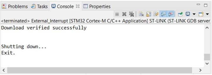
After a few moments, the code will be successfully sent to the STM32 board. You can view the message in the Console terminal.
Otherwise, press the RESET button on your STM32 board.
Now to bring the Blue pill back to normal mode make sure you bring the BOOT jumper back at its place. After doing that press the RESET button on the board.
Now press the push button. The LED will turn ON. Press the push button again. The LED will turn OFF. Likewise, keep on pressing the push button and the LED will keep on toggling.
Sometimes the LED will toggle inconsistently as well. This is because of the push button bouncing which can be interpreted as a single button press as many. To counter that, we can include a debouncing circuit to our circuit design.
Watch the demonstration video below:
STM32 Interrupt Latency
Interrupt Latency is the time when the interrupt was triggered to the time the event handler started execution. Ideally, we would want this time to be less. There are several factors that affect the interrupt latency including the microcontroller’s architecture/design, clock speed, type of interrupt controller used, and the operating system itself.
We will show you to measure the time taken when the external interrupt was triggered till the start of the ISR routine.
Now let us measure the interrupt latency of the example which we provided above where we used a push button to trigger the interrupt and toggled the LED pin. We will measure the time the CPU took to handle the external interrupt by changing the state of the LED pin using an oscilloscope.
THUMBS UP!
Tnx I missed one line and this document cleared it
This is the best tutorial blog for STM32 BLUEPILL… Thankyou