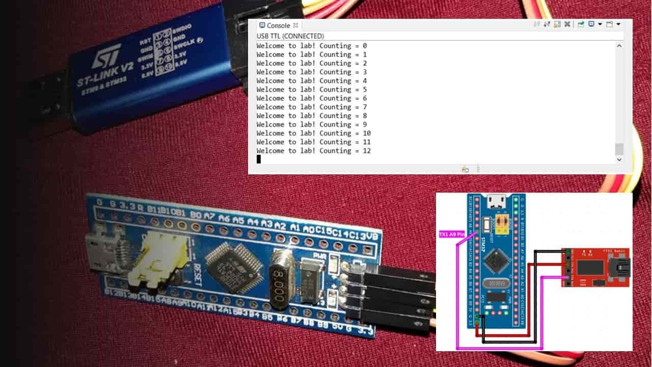
In this STM32 tutorial, we will learn how to use the UART communication channels of STM32 Blue Pill. We will see how to transmit and receive data through UART using STM32 CubeIDE and HAL libraries.
- We will be covering two projects in this guide. In the first project we will use the UART feature of Blue Pill to send serial data to our system’s serial COM port. By using a USB-TTL converter we will be able to display it on our terminal.
- In the second example, we will send data to STM32 Blue Pill from any serial terminal and transmit back the same data to the serial terminal. In other words, we will see example data transmit and receive in this example
Why use the UART Port of the STM32 Blue Pill?
Whenever we work on embedded system applications development sooner or later we need to use a serial communication protocol. We often use UART/USART to transfer data between microcontroller and computer for various purposes. One of the most important applications is to display data on the serial console of the computer for debugging or logging important events during program execution on a microcontroller. Furthermore, many wireless devices such as GSM, GPS, Bluetooth, Xbee, LoRA, and many others provide a serial interface to transfer data between these devices and a microcontroller.
In the last tutorials, we have seen how to use STM32 Blue Pill GPIO pins as digital output or digital input pins. You can read these articles on these links:
- STM32 Blue Pill GPIO Pins with STM32Cube IDE: LED Blinking Tutorial
- Push Button with STM32 Blue Pill using STM32Cube IDE – Read Digital Input Pins
- STM32 Blue Pill External Interrupts with STM32Cube IDE and HAL Libraries
STM32 Blue Pill UART Ports
Blue Pill STM32 consists of three UART modules: UART1, UART2, and UART3.
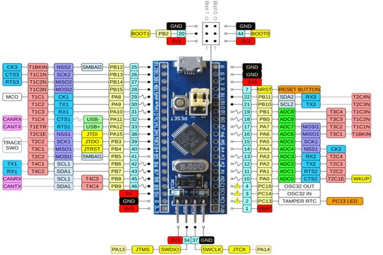
We can use any UART module for serial data transmission. However, you may have noticed that Blue Pill STM32 microcontroller does not have an onboard ST-Link debugger therefore we will need a USB-TTL converter.
One important thing to keep in mind is that pins for UART1 and UART3 are 5V tolerant however pins for UART2 are standard 3.3V pins.
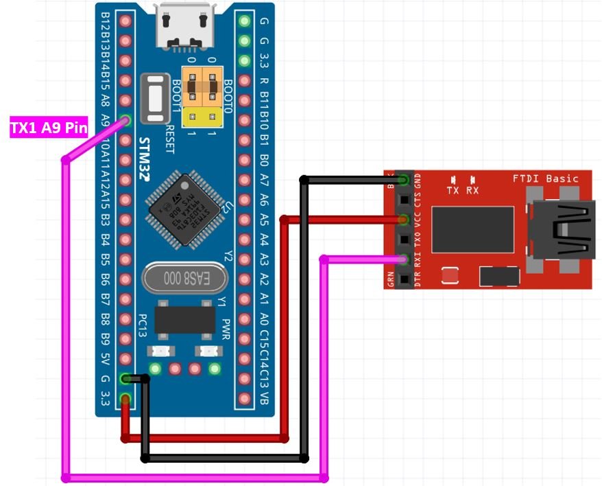
Connect FTDI USB to Serial with STM32 Blue Pill
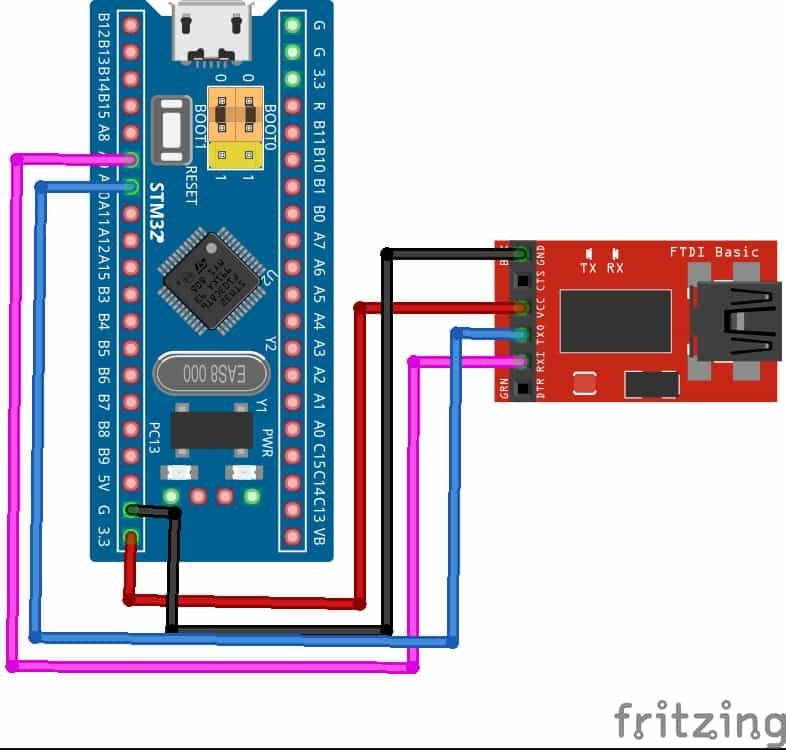
Let us show you how to connect the FTDI programmer with Blue pill STM32. As we will be transmitting serial data to the system, we will only connect the transmission pin TX1 with the RX pin of the programmer.
For this guide, we will use the UART1 module pins.
VCC of the programmer is connected with 3.3V from the Blue pill and both the GND of the devices are connected together.
STM32 Blue Pill UART Data Transmit Example
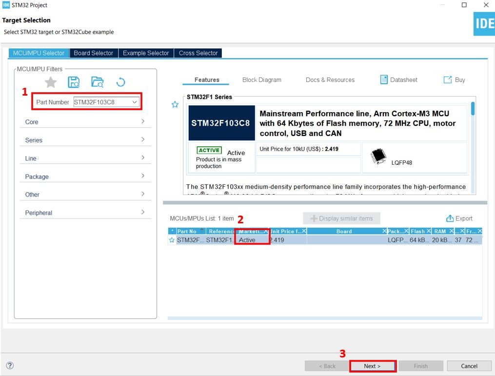
We will use STM32Cube IDE to program our STM32 board. Open the IDE and head over to a new project.
Then for the target selection, specify the STM32 Blue Pill board number. After that click on any column as shown in the picture below. Then click the ‘Next’ button.
The following window will open. Here specify the name of your project then click ‘Finish’ to complete the setup of your project.

Now head over to Connectivity > USART1 and set the mode as ‘Asynchronous.’

You can view the parameter settings of the UART including the baud rate, word length, parity, etc.

Now go to System Core > RCC then select ‘Crystal/Ceramic Resonator’ in from the High Speed Clock feature.
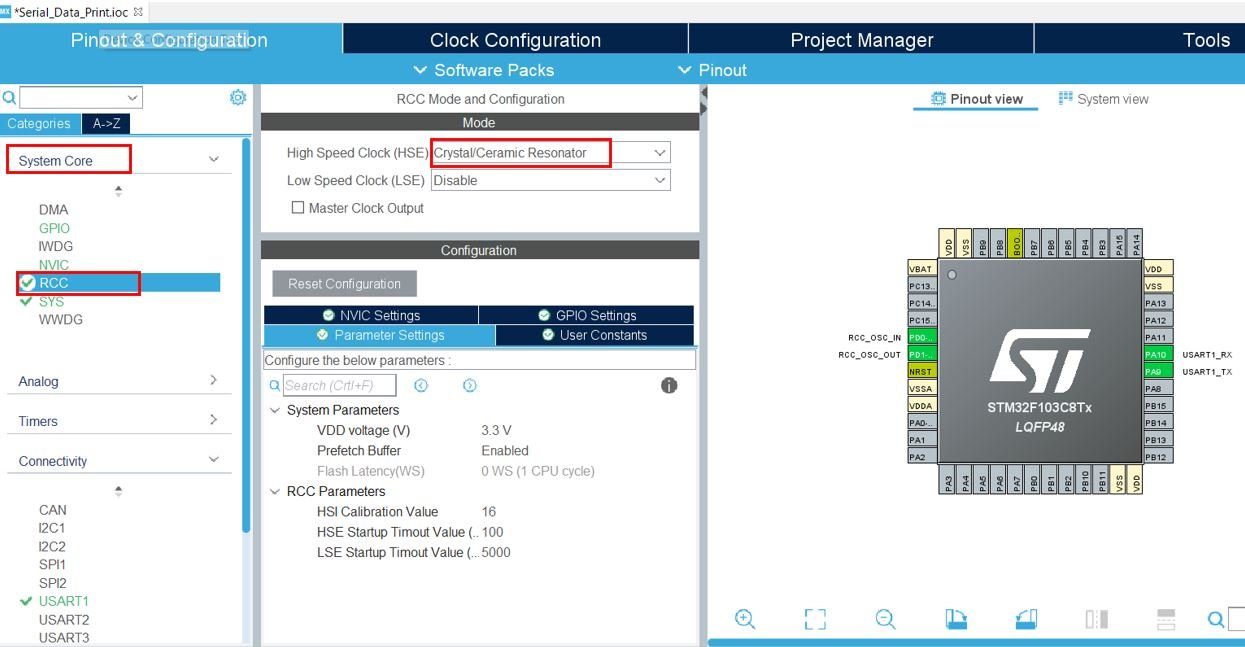
Now we have enabled the RCC external clock source.
Clock Configuration
Next go to the Clock Configuration found at the top. This will open the following window. Here we will select the clock frequency.
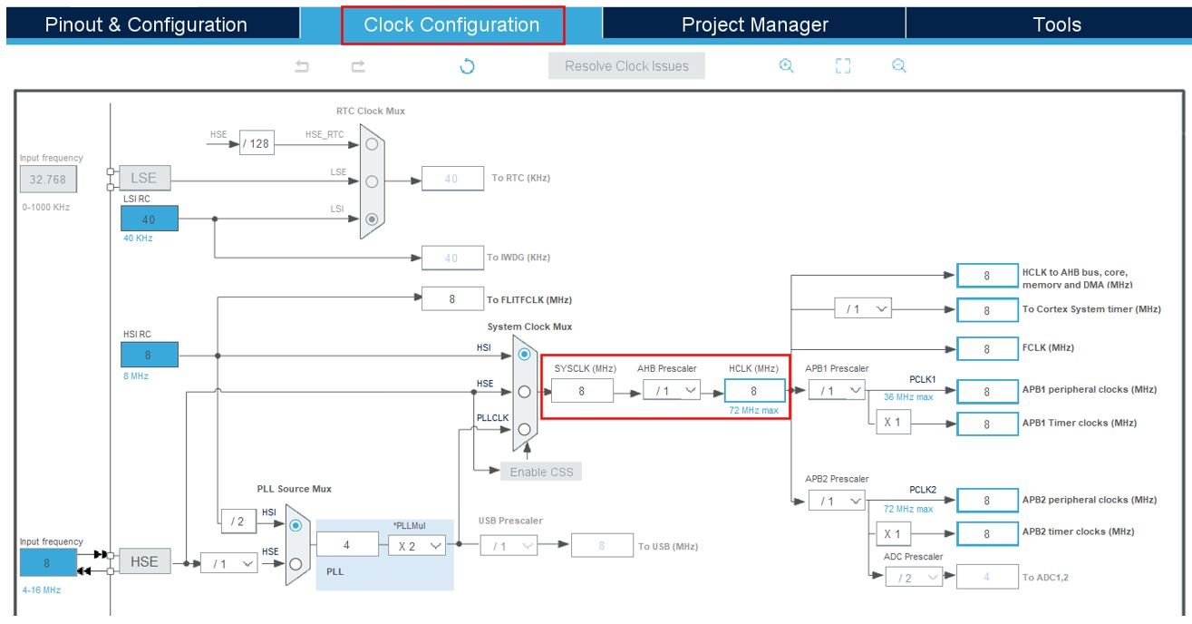
You can specify your system clock. We will set it as 72 MHz. These are the configurations we have set:

Now we will save our file. Press Ctrl + S. The following window will appear. Click ‘Yes.’ This will generate a template code for you.

Another window will appear that will ask if you want to open the perspective. Click ‘Yes.’

Serial Data Print with STM32 Blue Pill Code
Now the following page opens. On the right side, you will be able to view the Outline of the code. This happened because we opened our code with perspective. In the center, you can view the main.c file and on the left you can view Project Explorer. If you want to go to the Device Configuration Tool, then click the .ioc tab.
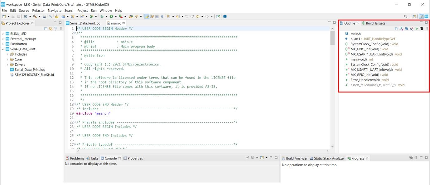
Now let us look at our main.c file that was generated.
Modifying Code
Inside the main.c file, look for the int main() function. Copy the code given below in the main() function.
int main(void)
{
	uint8_t message[35] = {'\0'};
	uint8_t num = 0;

	HAL_Init();

  SystemClock_Config();

  MX_GPIO_Init();
  MX_USART1_UART_Init();

  while (1)
  {
	  sprintf(message, "Welcome to lab! Counting = %d\r\n", num);
	  HAL_UART_Transmit(&huart1, message, sizeof(message), 100);
	  HAL_Delay(500);
	  num++;

  }

}
HAL UART Data Transmit Function
In Polling mode IO operation of UART module of STM32 Blue Pill, HAL_UART_Transmit() is used to send an amount of data in blocking mode HAL_UART_Receive() is used to receive an amount of data in blocking mode. These APIs are :
HAL_StatusTypeDef HAL_UART_Transmit(UART_HandleTypeDef *huart, uint8_t *pData, uint16_t Size, uint32_t Timeout)
- First parameter huart is a pointer to a UART_HandleTypeDef structure that contains the configuration information for the specified UART module.
- Second parameter pData is a Pointer to data buffer that we want to transmit
- Third parameter is the number of data elements (u8 or u16) to be sent
- Last parameter is a timeout duration for this function to retry.
- The return type of this function is a HAL status enum which contains status.
typedef enum
{
  HAL_OK       = 0x00U,
  HAL_ERROR    = 0x01U,
  HAL_BUSY     = 0x02U,
  HAL_TIMEOUT  = 0x03U
} HAL_StatusTypeDef;
In short, the above code will print messages with counter values on the system console after every 500ms.
main.c file
This is how a complete main.c file will be after modification.
#include "main.h"

UART_HandleTypeDef huart1;

void SystemClock_Config(void);
static void MX_GPIO_Init(void);
static void MX_USART1_UART_Init(void);

int main(void)
{
	uint8_t message[35] = {'\0'};
	uint8_t num = 0;

	HAL_Init();

  SystemClock_Config();

  MX_GPIO_Init();
  MX_USART1_UART_Init();

  while (1)
  {
	  sprintf(message, "Welcome to lab! Counting = %d\r\n", num);
	  HAL_UART_Transmit(&huart1, message, sizeof(message), 100);
	  HAL_Delay(500);
	  num++;

  }

}

/**
  * @brief System Clock Configuration
  * @retval None
  */
void SystemClock_Config(void)
{
  RCC_OscInitTypeDef RCC_OscInitStruct = {0};
  RCC_ClkInitTypeDef RCC_ClkInitStruct = {0};

  /** Initializes the RCC Oscillators according to the specified parameters
  * in the RCC_OscInitTypeDef structure.
  */
  RCC_OscInitStruct.OscillatorType = RCC_OSCILLATORTYPE_HSE;
  RCC_OscInitStruct.HSEState = RCC_HSE_ON;
  RCC_OscInitStruct.HSEPredivValue = RCC_HSE_PREDIV_DIV1;
  RCC_OscInitStruct.HSIState = RCC_HSI_ON;
  RCC_OscInitStruct.PLL.PLLState = RCC_PLL_ON;
  RCC_OscInitStruct.PLL.PLLSource = RCC_PLLSOURCE_HSE;
  RCC_OscInitStruct.PLL.PLLMUL = RCC_PLL_MUL9;
  if (HAL_RCC_OscConfig(&RCC_OscInitStruct) != HAL_OK)
  {
    Error_Handler();
  }
  /** Initializes the CPU, AHB and APB buses clocks
  */
  RCC_ClkInitStruct.ClockType = RCC_CLOCKTYPE_HCLK|RCC_CLOCKTYPE_SYSCLK
                              |RCC_CLOCKTYPE_PCLK1|RCC_CLOCKTYPE_PCLK2;
  RCC_ClkInitStruct.SYSCLKSource = RCC_SYSCLKSOURCE_PLLCLK;
  RCC_ClkInitStruct.AHBCLKDivider = RCC_SYSCLK_DIV1;
  RCC_ClkInitStruct.APB1CLKDivider = RCC_HCLK_DIV2;
  RCC_ClkInitStruct.APB2CLKDivider = RCC_HCLK_DIV1;

  if (HAL_RCC_ClockConfig(&RCC_ClkInitStruct, FLASH_LATENCY_2) != HAL_OK)
  {
    Error_Handler();
  }
}

/**
  * @brief USART1 Initialization Function
  * @param None
  * @retval None
  */
static void MX_USART1_UART_Init(void)
{
  /* USER CODE END USART1_Init 1 */
  huart1.Instance = USART1;
  huart1.Init.BaudRate = 115200;
  huart1.Init.WordLength = UART_WORDLENGTH_8B;
  huart1.Init.StopBits = UART_STOPBITS_1;
  huart1.Init.Parity = UART_PARITY_NONE;
  huart1.Init.Mode = UART_MODE_TX_RX;
  huart1.Init.HwFlowCtl = UART_HWCONTROL_NONE;
  huart1.Init.OverSampling = UART_OVERSAMPLING_16;
  if (HAL_UART_Init(&huart1) != HAL_OK)
  {
    Error_Handler();
  }

}

/**
  * @brief GPIO Initialization Function
  * @param None
  * @retval None
  */
static void MX_GPIO_Init(void)
{
  /* GPIO Ports Clock Enable */
  __HAL_RCC_GPIOD_CLK_ENABLE();
  __HAL_RCC_GPIOA_CLK_ENABLE();

}

void Error_Handler(void)
{
  __disable_irq();
  while (1)
  {
  }

}

#ifdef  USE_FULL_ASSERT
/**
  * @brief  Reports the name of the source file and the source line number
  *         where the assert_param error has occurred.
  * @param  file: pointer to the source file name
  * @param  line: assert_param error line source number
  * @retval None
  */
void assert_failed(uint8_t *file, uint32_t line)
{
  /* USER CODE BEGIN 6 */
  /* User can add his own implementation to report the file name and line number,
     ex: printf("Wrong parameters value: file %s on line %d\r\n", file, line) */
  /* USER CODE END 6 */
}
#endif /* USE_FULL_ASSERT */
Save the main.c file after modifying it. Now we are ready to build our project.
Building the Project
To build our project press Ctrl + B or go to Project > Build All.
Your project will start building. After a few moments, your project will be successfully built if there are no errors.

Connecting ST-Link Programmer with STM32
Now as we have successfully built our project let us move ahead and upload the code to our STM32 board. To do that, first we will have to connect our Blue Pill STM32 with a ST-Link programmer. We will be using ST-Link V2.

This will provide an interface between our computer and our STM32 board. It consists of 10 pins. We will be using pin2 SWDIO, pin6 SWCLK, pin4 GND, and pin8 3.3V to connect with our STM32 board. The SWDIO is the data input/output pin and the SWCLK is the clock pin. Follow the pin configuration given on the ST-LINK V2 to identify each pin.
Follow the table below to connect both devices correctly.
| STM32 | ST-LINK V2 |
| VCC 3.3V pin | pin8 3.3V |
| SWDIO pin | pin2 SWDIO |
| SWCLK pin | pin6 SWCLK |
| GND pin | pin4 GND |

Additionally move the BOOT jumper to the right to enable the microcontroller to go into programming mode.

Now connect your ST-LINK V2 with your computer via the USB port. Both the devices will power ON.
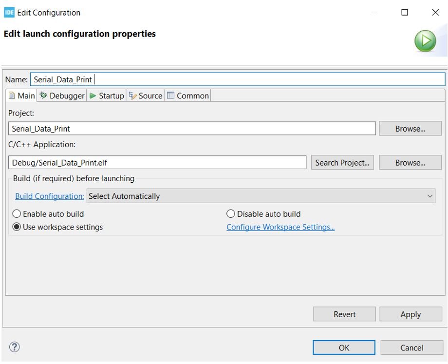
Next press the RUN button in the IDE. The ‘Edit configuration’ window will open up. Click ‘OK’.
After a few moments, the code will be successfully sent to the STM32 board.
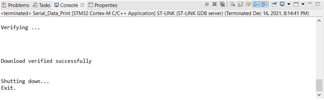
Otherwise, press the RESET button on your STM32 board.
Now to bring the Blue pill back to normal mode make sure you bring the BOOT jumper back at its place.
Now connect the USB to TTL serial converter with the STM32 board as mentioned previously. Open Device Manager and head over to Ports to check the COM port through which the USB-TTL converter is connected. It is COM5 in our case.

Open a terminal in your system to view the messages being transmitted by the board. Lets show you how to open a terminal from Cube IDE. First click the Open Console icon as shown below. Then click ‘Command Shell Console.’

Select the remote connection by first creating a New connection.

Specify the name of the connection, serial port and baud rate. Then click Finish to create a new connection.

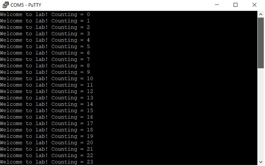
The console will open for the connection we set up. Press the Reset button of STM32 and the messages will start appearing on the console after every 0.5 seconds.

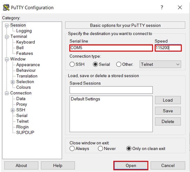
Additionally, we can use other terminals on our system as well for example Putty. Set the correct speed and COM port and then press Open to establish a connection.
Press the Reset button of STM32 and the messages will start appearing on the terminal after a short delay.
STM32 Blue Pill UART Data Receive Example
In the last section, we have seen how to send data with STM32 over UART. Similarly, we can also receive data from other devices over UART with STM32.
HAL UART Data Receive Function
HAL_UART_Receive function receives an amount of data in blocking mode or in polling method on the selected UART channel receive pin.
HAL_StatusTypeDef HAL_UART_Receive(UART_HandleTypeDef *huart, uint8_t *pData, uint16_t Size, uint32_t Timeout)
- First parameter huart is a pointer to a UART_HandleTypeDef structure that contains the configuration information for the specified UART module.
- Second parameter pData is a pointer to a data buffer in which we want to store received data
- Third parameter is the number of data elements (u8 or u16) to be received
- Last parameter is a timeout duration for this function to retry.
- The return type of this function is a HAL status enum which contains status
Now let’s modify the above code to receive data on the Rx/PA10 pin of STM32 Blue Pill. As you know that we are using the UART1 channel in this tutorial. So the receiver pin for the UART1 port is PA10. Make a connection between STM32 Blue Pill and USB to the serial converter by connecting Rx/PA10 pin with Tx pin of FTDI converter:
STM32 UART Data Receive Code
Now modify the main.c file with the following code:
int main(void)
{
        char Message[] = "Write anything on Serial Terminal\r\n"; /* Message to be transmitted through UART */
	uint8_t num = 0;

	HAL_Init();

  SystemClock_Config();

  MX_GPIO_Init();
  MX_USART1_UART_Init();
  HAL_UART_Transmit(&huart1, (uint8_t *)Message, strlen(Message), 10);

  while (1)
  {
     uint8_t buffer[4];
     HAL_UART_Receive(&huart1, buffer, sizeof(buffer), HAL_MAX_DELAY);
     HAL_UART_Transmit(&huart1, buffer, sizeof(buffer), HAL_MAX_DELAY);
  }

}
The above will code echo back whatever it will receive on the Rx pin to the terminal. In other words. Whatever you type on the serial terminal, it will be sent to the STM32 Plue Pill and STM32 will transmit it back to the computer through UART transmit function that is HAL_UART_Transmit().
Follow the same steps as mentioned above to open the serial console after uploading code to the STM32 Blue pill and you will get the following output:

In summary, we learned the following in this tutorial:
- STM32 Blue Pill UART Ports and channels
- HAL USART/UART Driver
- How to use STM32F4 UART in polling mode
- How to transmit data with STM32 UART
- How to receive data with STM32 UART
5/5 : Great tutorial.
You are guided through each step and it is well explained.
Thank you
Thanks a lot for this tutorial. Was able to see and understand the output, except at the last portion.
I am getting a ‘USB-TTL closed’ error when I try the last portion of the experiment (TX and RX). Either only Putty works or the Command Shell console works. Not able to see the echoing.
Could you please help?