In this tutorial, we will discuss about STM32 I2C communication modes, hardware overview and functionalities, I2C interrupts, handling I2C transactions for both master and slave including HAL APIs for I2C for different I2C modes.
Recommended Components
The following components are used in this project or are helpful for getting started with STM32 Blue Pill development.
| Component | How it’s used in this project | Buy on Amazon |
|---|---|---|
| STM32F103C8T6 Blue Pill Board | The STM32 board whose I2C peripheral is covered in this guide. | Check Price |
| ST-Link V2 Programmer | SWD programmer/debugger used to flash code onto the Blue Pill. | Check Price |
| Breadboard & Jumper Wires | For wiring the I2C bus between master and slave devices. | Check Price |
As an Amazon Associate we earn from qualifying purchases. Prices and availability are accurate as of the date/time indicated and are subject to change.
STM32 I2C Introduction
In this section, let us now focus on the I2C hardware module of STM32 including its features, modes of operations and data transactions.
The I2C bus acts as an interface between the STM32 board and the I2C serial bus. It is responsible for controlling all the I2C bus timing and sequencing and multi master capability. The STM32 on-chip IC supports the standard and the fast mode for the I2C bus.
The diagram below shows the block diagram of the I2C module in STM32.

The module consists of a shift and data register, along with control logic for the DMA requests and ACK and interrupts. The I2C transaction steps are all handled which include address match check, clock control, noise filter, error check etc.
Key Features
Lets list some of the key features of the STM32 I2C protocol:
- Has multi-master capability meaning that it can act both as a master and as a slave
- The I2C master features clock, start and stop generation.
- The I2C slave features stop bit detection, I2C address detection which is programmable in nature and dual address capability.
- Is operable on two bus speeds: standard (maximum 100 kHz) and fast (maximum 400 kHz).
- Contains an analog noise filter
- Generates and detects 7 bit and 10 bit addressing
- Has compatibility of SMBus 2.0 and PMBus
- Packet Error Checking (PEC) generation/verification can also be configured
- Has a buffer of 1 byte for DMA
- Features one interrupt for data communication and another for the error condition.
STM32 I2C Modes
The I2C interface for STM32 can be configured in four modes. The STM32 boards can either act as a slave transmitter, slave receiver, master transmitter or master receiver. By default, the slave mode is being used. Multi master capability is also a feature of this module, where the board automatically changes from being a slave to a master and vice versa according to the start, stop conditions or occurrence of arbitration loss.
Lets look at each of these four modes closely.
I2C Slave Mode (receiver and transmitter)
As mentioned previously, the I2C mode by default is set in slave mode. The peripheral input clock is of high importance as it governs the correct timings according to the values set in the I2C_CR2 register. Moreover, when using in standard mode, the input clock frequency should have a minimum value of 2MHz. Likewise, when using in fast mode, 4MHz minimum input clock frequency is required.
When the mode switches from slave to master, a Start condition is generated. When the detection of this condition, the shift register receives the address from the SDA line. This address is then compared to the address of the interface. The internal shift register is responsible for sending the received bytes from the SDA line to the DR register. This happens after the address is received and the ADDR is wiped off. The interface then produces an acknowledge signal when the ACK bit is set, for every byte.
Before the end of the next data reception, if the data in the DR register is not read considering the RxNE flag is also configured, then the BTF is set and the I2C interface stands by until the BTF is cleared. The I2C_SR1 reads the BTF which clears it. After that, the I2C_DR register reads it and sets the SCL line to a LOW state. A stop condition is produced by the master when the last data byte is sent. If an interrupt was set (ITEVFEN bit), then an interrupt will be generated when the I2C interface catches the stop condition. At this moment, the STOPF bit gets cleared when the SR1 register reads it and writes it to the CR1 register.
An important concept here is ‘clock stretching’. In this process, the slave holds the state of the SCL line is LOW. This ensures that the master device does not start a new data transaction until the slave is ready to do so, after it releases the SCL line again.
I2C Master Mode (receiver and transmitter)
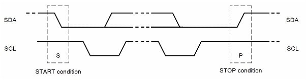
Now lets look at the I2C master mode which is responsible for generating the clock signal and starting the data transfer. Each I²C command initiated by a master device starts with a START condition and ends with a STOP condition. For both conditions, SCL has to be high. After the Start condition, the bus is considered busy and can be used by another master only after a Stop condition is detected.
The master device pulls SDA (serial data) low and leaves SCL (serial clock) high in order to start the address frame. It alerts all the slave devices that a transmission is going to get started. If there are two or more master devices, then whichever master device brings the SDA low first will take ownership of the bus.
- Start condition: A high to low transition of SDA.
- Stop condition: A low to high transition of SDA.
Lets look the sequence of steps that are followed by the master device for initiating data transaction.
- Firstly, the I2C_CR2 register is programmed in such a manner for the peripheral input clock to produce correct timings.
- Next, the clock control registers and the rise time register is configured.
- The peripheral is enabled by programming the I2C_CR1 register.
- Finally, the START condition is generated by setting the START bit in the I2C_CR1 register.
Moreover, when using in standard mode, the peripheral input clock frequency should have a minimum value of 2MHz. Likewise, when using in fast mode, 4MHz minimum peripheral input clock frequency is required.
STM32 I2C Packet Error Checking
One of the great features of STM32 I2C module is the implementation of PEC which is packet error checking mechanism. This is to enhance the reliability of the I2C communication. This packet error checking mechanism helps to automatically detect errors without involving software by inspecting large data packet transactions. One important thing to note here is that if the master loses an arbitration at any point, then the device goes back to slave mode as the packet error checking got corrupted. When the master completes its data transaction, then the process starts again and the slave device has to wait all this time.
To calculate the PEC, the following CRC-8 polynomial formula is used serially on every bit:
C(x) = x8 + x2 + x + 1
STM32 I2C Error Conditions
The STM32 I2C module also offers detection of error conditions that occur on the hardware level. The table below shows the error conditions which can be monitored and checked through their respective flag bits associated with each error signal.
| BERR (Bus Error) | The bus error occurs if an external start/stop condition is detected in the course of data transfer/address. |
| AF (Acknowledge Error) | If a non-acknowledge bit is detected, then this error occurs. |
| ARLO (Arbitration Lost Error) | This error occurs whenever an arbitration lost condition happens. |
| OVR (Overrun/Underrun Error) | The overrun error occurs when the device which is working as a slave with disabled clock stretching, receives data. Such a situation exists when the interface receives a byte of data when it has not been read in DR before the next byte is received by the interface. However, the underrun error occurs when the device which is working as a slave with disabled clock stretching, transmits data. Such a situation exists when the interface has not updated the DR with the next byte before the clock comes for the next byte. |
STM32 I2C Interrupts
The STM32 I2C module also features interrupt events which when detected cause an interrupt to be triggered which the software detects. Each interrupt event has its own specific enable control bit which is set whenever an interrupt is generated.
The table below lists the I2C interrupt requests along with their event flags and the corresponding enable control bits:
| Interrupt Event | Event Flag | Enable Control Bit |
| Start Bit Sent (Master) | SB | ITEVFEN |
| Address Sent (Master) or Address Matched (Slave) | ADDR | ITEVFEN |
| 10-bit Header Sent (Master) | ADD10 | ITEVFEN |
| Stop Received (Slave) | STOPF | ITEVFEN |
| Data Byte Transfer Finished | BTF | ITEVFEN |
| Receive Buffer Not Empty | RxNE | ITEVFEN & ITBUFEN |
| Transmit Buffer Empty | TxE | ITEVFEN & ITBUFEN |
STM32 I2C Master Transmission and Reception (Tx & RX)
STM32 I2C data transmission and reception can be handled in three different ways blocking/n-blocking which means that the I2C module can be configured differently for each case.
I2C with Polling Mode
The I2C module when configured in polling mode works in blocking mode. It is one of the simplest configurations where the CPU waits until the current byte of data is transmitted and then sends the next one and so on. After the data transmission completes, the CPU starts again and continues with the execution of the main code. Both data transmission and reception works in the same way, where there is a wait state between each data transaction. This causes this method to be a bit inefficient as the CPU spends a lot of precious time waiting.
I2C with Interrupt Mode
The I2C module when configured in polling mode works in non-blocking mode. Unlike the polling method, the CPU does not stop but continues the execution of the main code. The completion of the data transaction marks the triggering of the interrupt. The signal is generated when it is time for servicing by the CPU. This works for both data transmission and data reception. This method reduces a lot of time that was wasted before in the polling mode. However, using the interrupt method with high rate of transactions can however overload the CPU and they may also potentially harm the timing of the system.
I2C with DMA Mode
In this scenario, the I2C module is configured in non-blocking mode where the DMA sends the data transactions from the peripheral to the memory directly. The CPU is not involved as was the case in polling and interrupt. It frees the CPU from all the data transfers thus making the system very time efficient. It uses a basic request/acknowledge protocol. The data register generates the DMA request by emptying the register during data transmission and filling it completely during data reception.
STM32 I2C Device Memory Read / Write
Most of the functions that we already discussed related to the I2C interface occur automatically by the hardware through the setting and clearing of the control bits. To set the configuration of the set/clear bits of the control registers, some simple functions are used.
Master Data TX
One of the most commonly used HAL function to initiate data transfer over I2C protocol for a master is as follows:
HAL_StatusTypeDef HAL_I2C_Master_Transmit(I2C_HandleTypeDef * hi2c,
 uint16_t DevAddress,
 uint8_t * pData,
 uint16_t Size,
 uint32_t Timeout
)
This function transmits an amount of data in master mode in blocking mode. This function takes in several parameters which include:
- Pointer to the I2C_HandleTypeDef structure that holds the configuration parameters for the specified I2C.
- Target device address
- Pointer to the data buffer
- Size of the data to be sent
- Duration of the timeout
The Master_Transmit collection of functions are available for all three modes: blocking, interrupt and DMA.
Device Memory Write
However, we have HAL APIs for the I2C driver firmware library which is the device memory read/write for all three operable modes as well. In blocking mode, the API for memory write is shown below:
HAL_StatusTypeDef HAL_I2C_Mem_Write(I2C_HandleTypeDef * hi2c,
 uint16_t DevAddress,
 uint16_t MemAddress,
 uint16_t  MemAddSize,
 uint8_t * pData,
 uint16_t Size,
 uint32_t Timeout
)
This function is used to write an amount of data in blocking mode to a particular memory address. This function takes in several parameters which include:
- Pointer to the I2C_HandleTypeDef structure that holds the configuration parameters for the specified I2C.
- Target device address
- Internal memory address
- Size of the internal memory address
- Pointer to the data buffer
- Size of the data to be sent
- Duration of the timeout
Lets understand the basic difference between I2C_Transmit() and I2C_Mem_Write() through an example of an I2C sensor for example MPU6050 which acts as an I2C slave. This device has its own unique internal I2C device address which is used by the master to identify the sensor module and address it. This address is held inside the registers present inside the sensor. In order to configure the sensor according to our needs, we have to set/read the value of these internal registers accordingly.
So what happens when the master STM32 microcontroller wants to access the readings of the slave I2C sensor. The table below shows the single byte read sequence that follows between the master and the slave.
| Master | S | AD+W | RA | S | AD+R | NACK | P | ||||
| Slave | ACK | ACK | ACK | DATA |
As you can see in the table above, the master initiates the transaction and then sends AD+W, address of the slave along with write operation. This will cause the master to write the register address RA inside the slave that it wants to read. The slave acknowledges (ACK) the command and sends the data present in the particular register. The master will then end the I2C communication. This is how a register is read from a particular address inside the slave which has its own address on the I2C bus.
Using CubeMX IDE to Configure I2C Mode
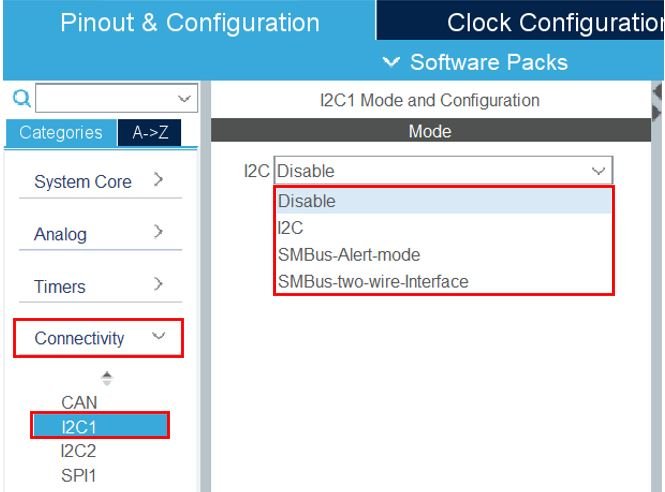
To program STM32 microcontroller in I2C mode for data transmission and reception we use STMCube IDE to configure all the parameters. First of all head over to Connectivity and select the I2C channel. STM32 Blue Pill consists of two I2C channels, I2C1 and I2C2. After selecting the channel, you will have to select the I2C mode from the list shown below.
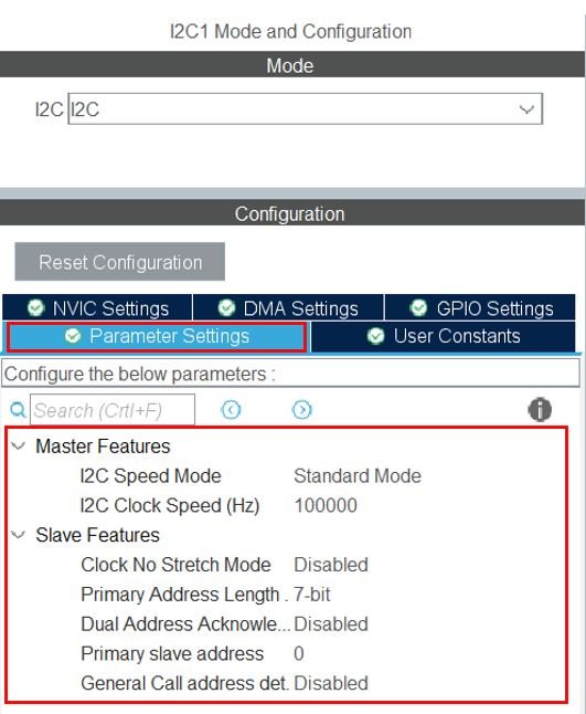
After selecting the mode as ‘I2C’, you will be able to view the parameter settings. This includes the I2C speed mode and clock speed for the master. For the I2C slave, we can set the I2C device address length, value and enable/disable the clock in no stretch mode etc.
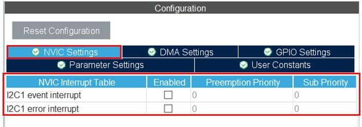
Moreover, the user can head over to NVIC Settings to enable the event and error interrupt, if using the interrupt mode.
Similarly, the user can configure the DMA mode, by heading over to DMA Settings and adding the DMA request for I2C TX and I2C RX according to the I2C channel selected.
STM32 I2C HAL APIs
In this section, we will discuss some important HAL APIs related to STM32 I2C module which includes all the three modes.
STM32 I2C Data Transmission and Reception in Blocking Mode
The following function is used to transmit an amount of data in master mode in blocking mode.
HAL_I2C_Master_Transmit (I2C_HandleTypeDef * hi2c, uint16_t DevAddress, uint8_t* pData, uint16_t Size, uint32_t Timeout);
Likewise, this function is used to receive an amount of data in master mode in blocking mode.
HAL_I2C_Master_Receive (I2C_HandleTypeDef * hi2c, uint16_t DevAddress, uint8_t* pData, uint16_t Size, uint32_t Timeout);
For the slave in blocking mode, the following function is used to transmit an amount of data.
HAL_I2C_Slave_Transmit (I2C_HandleTypeDef * hi2c, uint8_t * pData, uint16_t Size, uint32_t Timeout);
Similarly, the following function is used to receive an amount of data in slave mode in blocking mode.
HAL_I2C_Slave_Receive (I2C_HandleTypeDef * hi2c, uint8_t * pData, uint16_t Size, uint32_t Timeout);STM32 I2C Data Transmission and Reception in Interrupt Mode
When using the I2C module in interrupt mode, the following function will transmit an amount of data in master mode, in non-blocking mode with interrupt.
HAL_I2C_Master_Transmit_IT (I2C_HandleTypeDef * hi2c, uint16_t DevAddress, uint8_t * pData, uint16_t Size);
Similarly, the following function will be called to receive an amount of data in master mode, in non-blocking mode with interrupt.
HAL_I2C_Master_Receive_IT (I2C_HandleTypeDef * hi2c, uint16_t DevAddress, uint8_t * pData, uint16_t Size);
STM32 IC Data Transmission and Reception in DMA Mode
This function is used to transmit an amount of data in master mode, in non-blocking mode with DMA.
HAL_I2C_Master_Transmit_DMA (I2C_HandleTypeDef * hi2c, uint16_t DevAddress, uint8_t * pData, uint16_t Size);
The following function will receive an amount of data in master mode, in non-blocking mode with DMA.
HAL_I2C_Master_Receive_DMA (I2C_HandleTypeDef * hi2c, uint16_t DevAddress, uint8_t * pData, uint16_t Size);
Device Memory Write/Read
This function is used to write an amount of data in blocking mode to a particular memory address.
HAL_I2C_Mem_Write (I2C_HandleTypeDef * hi2c, uint16_t DevAddress, uint16_t MemAddress, uint16_t MemAddSize, uint8_t * pData, uint16_t Size, uint32_t Timeout);
This function is used to read an amount of data in blocking mode to a particular memory address.
HAL_I2C_Mem_Read (I2C_HandleTypeDef * hi2c, uint16_t DevAddress, uint16_t MemAddress, uint16_t MemAddSize, uint8_t * pData, uint16_t Size, uint32_t Timeout);
You can read following tutorials where we used I2C channels of STM32 Blue Pill to interface different display and get readings from different sensors: