In this tutorial, we will learn how to generate a delay with a systick timer interrupt of TM4C123 microcontroller. We will toggle an LED with a delay of 1 second using the interrupt service routine of the systick timer handler function. In the last tutorial, we have discussed the in-depth introduction of the systick timer module of TM4C123 ARM Cortex M4 microcontroller. In that tutorial, we have learned to use a systick timer and how to configure control and status registers of the system timer. We have seen an example to generate 1 second delay, but we used a polling method. In this tutorial, we will see an example of an interrupt method.
You can read that post on this link:
Systick Interrupt Introduction
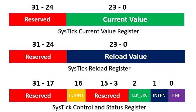
Systick timer has three configuration and control registers. But STCTRL (systick control and status register is the main register which is used to configure the timer. It is a 32-bit register, but only four bits are used such as ENABLE, INTEN, CLK_SCR and COUNT bits. Rest of the bits are reserved as shown in figure below:

INTEN bit enables or disables the interrupt functionality of systick timer. If we set the INTEN bit ( INTEN=1), it enables the systick interrupt. That means, whenever the counter reaches zero from a reload value, the systick timer requests the interrupt signal to the nested interrupt vector controller (NVIC) of TM4C123 microcontroller.
For example, if we load the number 100 to reload the register and the clock frequency of TM4C123 microcontroller is 16MHz. That means counter value will decrement by 1 after every 1/16MHz or 62.5 nanoseconds. Therefore, the counter value will reach to zero after 101 x 62.5ns or :
101 x 62.5 = 6.3125ms
Hence, after 6.3125ms, the systick timer set the count flag bit of STCTRL register which will send the interrupt signal to nested interrupt vector controller.
Systick Interrupt Applications
Followings are the important applications with interrupt method:
- It can be used to create periodic tasks that will execute after pre-defined interval of time
- It can be used to synchrozie tasks execution in periodic manner
For example, we have one task in our application that reads current sensor value and we want to measure current value after every 100ms second. By using systick interrupt, we can enable the current sensor task execution. That means, the task will remain in the blocking state untill interrupt occurs. When systick timer interrupt occurs, the current sensor task will take one measurement and go back to blocked state untill next interrupt. These concepts are used in real time operating sytems.
You can read our complete FreeRTOS tutorials list here:
Using Systick Interrupt Module
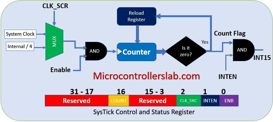
As we have discussed in last section, when counter value reaches zero, it will set counter flag bit (bit 16 of STCTRL register) which will generate an systick interrupt request to nested interrupt vector controller. The nested interrupt vector controllers reads this interrupt and tranfers the CPU from thread handler mode to exception hanlder mode. In this mode, CPU reads the respective interrupt singal and executes its respective handler routine.
Systick Interrupt Block Diagram
If you see the interrupt vector table of TM4C123, the systick interrupt has number 15 or INT15.

As we have seen in TM4C123G microcontroller startup file tutorial that the startup file contains weak definition of all interrupts and exception routines. These ISR routines are defined with weak attributes that means we can redefine them inside our main code according to our requirement. But the name of a specific ISR routine should remain the same.
Systick Handler function
For example, the name of the systick interrupt service routine in the startup file of TM4C123G microcontroller in Keil compiler is SysTick_Handler.
Void SysTick_Handler (void)
{ //instructions  }
Generate Delay with Systick Interrupt
This program will generate a delay of 1 second. In other words, the systick timer interrupt will occur after one second. To generate interrupt after every second, the value of reload register will be:
Reload =  (require delay / clock tim_period) - 1
Reload = ( 1 / 1/16MHz) - 1 = 16000000 - 1 = 1599999
Where 16MHz is a clock frequency of TM4C123 microcontroller. Hence, we will load system timer relaod register with 1599999. The count flag bit will become one and generate interrupt everytime the counter down counts from 1599999 to 0. After interrupt, the count register will be automatically loaded with 1599999.
Code
This example code generates a delay of one second. using an interrupt of systick timer and to demonstrate this, we will turn on and turn off onboard Green LED which is connected with PF3 pin of the Tiva launchpad.
This code uses an interrupt method instead of a polling method to toggle LED after one second. As you can see inside the while loop, we are doing nothing instead we have written a logic to turn on the LED inside the systick handler function.
#include "TM4C123GH6PM.h"
int main()
{
  SYSCTL->RCGCGPIO |= 0x20; // turn on bus clock for GPIOF
  GPIOF->DIR       |= 0x08; //set GREEN pin as a digital output pin
  GPIOF->DEN       |= 0x08;  // Enable PF3 pin as a digital pin

	SysTick->LOAD = 15999999; // one second delay relaod value
	SysTick->CTRL = 7 ; // enable counter, interrupt and select system bus clock
	SysTick->VAL  = 0; //initialize current value register

	while (1)
	{
		//do nothing here
	}
}

// this routine will execute after every one second

void SysTick_Handler(void)
{
   GPIOF->DATA  ^= 8;  //toggle PF3 pin

}
This line enables the clock for GPIO Port F. The value 0x20 is the hexadecimal representation of the bit mask to enable the clock for Port F.
SYSCTL->RCGCGPIO |= 0x20; // turn on bus clock for GPIOFGPIOF->DIR |= 0x08; sets the direction of PF3 as an output (the green LED pin). GPIOF->DEN |= 0x08; enables the PF3 pin as a digital pin (i.e., it will be used as a digital I/O pin).
GPIOF->DIR |= 0x08; // set GREEN pin as a digital output pin
GPIOF->DEN |= 0x08; // Enable PF3 pin as a digital pin
SysTick->LOAD = 15999999; sets the reload value for the SysTick timer. This value corresponds to a 1-second delay assuming the system clock is running at 16 MHz. The SysTick timer counts down from this value to 0, generating an interrupt when it reaches 0.SysTick->CTRL = 7; enables the SysTick timer, its interrupt, and selects the system clock as the clock source. The value 7 is a bit mask that turns on the counter (1), enables the interrupt (2), and chooses the system clock (4).SysTick->VAL = 0; initializes the current value register to 0, ensuring the timer starts counting down from the reload value.
SysTick->LOAD = 15999999; // one second delay reload value
SysTick->CTRL = 7;        // enable counter, interrupt, and select system bus clock
SysTick->VAL  = 0;        // initialize current value register
This function is the SysTick interrupt handler, which is automatically called when the SysTick timer reaches 0.GPIOF->DATA ^= 8; toggles the state of the PF3 pin (connected to the green LED). The XOR operation with 8 (binary 00001000) flips the bit, causing the LED to turn on if it was off, or off if it was on.
void SysTick_Handler(void)
{
    GPIOF->DATA ^= 8;  // toggle PF3 pin
}
This function is the SysTick interrupt handler, which is automatically called when the SysTick timer reaches 0.GPIOF->DATA ^= 8; toggles the state of the PF3 pin (connected to the green LED). The XOR operation with 8 (binary 00001000) flips the bit, causing the LED to turn on if it was off, or off if it was on.
Video Demo
Other TM4C123G Tiv C Tutorials:
- UART Communication TM4C123 Tiva C Launchpad
- UART Interrupt TM4C123G Tiva C Launchpad
- How to use GPIO pins of TM4C123G Tiva launchPad
- Use Push Button to Control LED with TM4C123G Tiva LaunchPad
- Accessing Memory Mapped Peripherals Registers of Microcontrollers
- Bare-metal and RTOS Based Embedded Systems
- What is Interrupt Vector Table?
hi , thanks
i want to have 1 sec time for do my project before the systick timer start , means that systick must run after 1 sec form start progrm
please help me , thank you