In this tutorial, we will see what is a systick timer or system timer in TM4C123G ARM Cortex M4 microcontroller. We will start with an introduction of a systick timer and discuss some of its major applications. In the concluding section of this tutorial, we will see an example of Systick timer and learn to configure system timer control registers of TM4C123GH6PM microcontroller using Tiva Launchpad.
Recommended Components
The following components are used in this project or are helpful for getting started with TM4C123 Tiva C LaunchPad development.
| Component | How it’s used in this project | Buy on Amazon |
|---|---|---|
| TM4C123G Tiva C LaunchPad | Provides the ARM Cortex M4 SysTick timer demonstrated in this tutorial | Check Price |
| Micro USB Cable | Programs and powers the LaunchPad via onboard ICDI debugger | Check Price |
As an Amazon Associate we earn from qualifying purchases. Prices and availability are accurate as of the date/time indicated and are subject to change.
SysTick Timer Introduction
Systick timer is a dedicated hardware-based timer which is built inside the ARM Cortex M4 CPU and can be used to generate an interrupt at a fixed interval of time. As shown in the figure below:

The systick timer will generate interrupts after a specified time and time settings can be done using the Systick control register ( will be discussed later).
TM4C123G Microcontroller System Timer
TM4C123GH6PM ARM Cortex M4 microcontroller provides a 24-bit system timer that supports down decrement feature. That means it counts downwards starting from a preloaded or set value. The rate of value decrement depends on the system clock frequency and we can set the value of clock frequency using a control register which is associated with the Systick timer. We will see the details of configuration register in the later part of this tutorial.
Applications
Following are the some of the applications of systick timer
- Generate delays
- Introducing time delays between two events
- Calling periodic tasks after a specified time e.g. RTOS tick timer
- Used to implements time-share scheduling in RTOS
How does the Systick timer work?
TM4C123GH6PM provides a 24 bit timer. Therefore, the maximum value that can be loaded to the load register of system timer is 2^(24-1) which is . Hence, it starts decrement value by one from its initial set value and generates an interrupt when values reaches zero.
In all ARM cortex M4 microcontrollers, the nested vectored interrupt controller manages interrupts or exceptions generated by peripherals or GPIO pins. Hence, whenever a Systick timer interrupt occurs, the nested interrupt vector controller transfers the control of CPU to the related interrupt service routine.
As we have seen in the TM4C123G microcontroller startup file tutorial that the startup file contains a weak definition of all interrupts and exception routines. These ISR routines are defined with weak attributes that means we can redefine them inside our main code according to our requirement. But the name of a specific ISR routine should remain the same.
For example, the name of the systick interrupt service routine in the startup file of TM4C123G microcontroller in Keil compiler is SysTick_Handler.
Void SysTick_Handler (void)
{ //instructions  }
Systick Timer Block Diagram
This figure given below depicts the working behavior of a systick timer of ARM cortex M4 microcontroller:
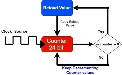
As you know that the system timer of TM4C123G microcontroller is a 24-bit down counter. We reload the initial value to reload register and counter decrements from reload value to zero. The value of the counter decrements on every positive edge of the clock cycle. When counter values reach zero, the system timer generates an interrupt. Also, the counter is re-initialized with reload value again. Hence, the process keeps repeating.
How to use Systick timer of TM4C123G MCU
For example, the frequency of the clock given to the systick timer is 10MHz. Therefore, the time period will be T = 1/f = 1/10MHz = 0.1us. That means, the value of the counter decrements after every 0.1us.
By using this clock period value, we can calculate the time after which the systick counter reaches to zero value.
Systick timer interrupt time period = (Reload value + 1 ) x time period
You must be thinking, we need to add 1 to reload value? This is because down counter decrements from reload value to zero. Hence, the counter goes through a total of one plus the reload value.
For example, if the reload value is 20 and TM4C123G operating frequency is 10MHz, what will be the systick interrupt time period? According to the above equation,
Systick timer interrupt time = (20+1) x 1/10MHz = 21 x 0.1us = 2.1us
In summary, the system timer will reach from reload value to zero in 2.1 microseconds. In the later section of this tutorial, we will see how to generate the desired time delay with the systick timer interrupt.
Systick Timer Registers
In TM4C123GM6PM microcontroller, there are three registers associated with the system timer module such as control register, reload value and current value registers. Now lets discuss these three timers and their function one by one:
SysTick Control and Status (STCTRL)
This register is used to configure the clock for the systick timer, enable counter, enable the systick interrupt, and provide the status of the counter. It is a 32-bit register but only 4 bits are used and reset of the bits are reserved as shown in the figure below:

ENABLE Bit 0
This bit enables or disables the counter. Setting this bit of STCRL enables the 24-bit counter and clearing it disables the counter.
INTEN Bit 1
Interrupt control bit sends the request to the nested interrupt vector controller. when the counter value reaches 0. Setting INTEN bit to 1 enables the interrupt and clearing it disables the systick timer interrupt. Therefore, if you want to enable interrupt of system timer on every down count to zero, you should enable this bit of control and status register.
CLK_SRC Bit 2
It is a clock source selection bit. We have options to select a clock from either system clock or Precision internal oscillator (PIOSC) divided by 4. Setting CLK_SRC bit to 1 selects the system clock of TM4C123G microcontroller and clearing it selects the internal oscillator (PIOSC) divided by 4. But we usually use system clock settings. But it also depends on your project requirement and timing delays requirement.
COUNT Bit 16
This is a counter flag or status bit for the counter. This bit becomes 1 when counter decrements from 0 to one.

SysTick Reload Value Register (STRELOAD)
This register holds the reload value that will be copied to counter on every systick interrupt. In other words, the counter is re-initialized with a reload register value on every count down to zero. We save the reload value in this register ( we will see this in the programming section). STRELOAD register is a 32-bit register but only the first 24-bits are used and the rest of the bits are reserved. Because the systick timer has a 24-bit counter.

For example, if we want to generate an interrupt after every 100 clock pulses of the system clock, you should reload 99 to this register.
SysTick Current Value Register (STCURRENT)
As its name suggests, this register holds the current value of the counter. For instance, you want to perform some action after clock pulses, you can read the value of this register and perform an action. If you this register value, it will return the current value of the counter.

Caculate Reload Value to Create Timing Delay
Let’s make this calculator for TM4C123G microcontroller. As you know that TM4C123G has 16MHz of clock bus and we want to use a bus clock.
Systick Timer interrupt Time period  = (Reload+1) x (clock_bus_time_period)
Reload  =  (required delay / Clock Period) - 1;
Reload = ( 1 / 1/16Mz ) - 1 = 16MHz - 1 = 16000000 - 1 = 15999999
Hence, to get 1 one second delay, you should load this value to the reload register. By using this formual , we can caculate any required delay:
Reload = (Interrupt delay / Clock Period) - 1;
But, it should be noted that the value of reload register should not be greater than the maximum value a 24-bit register can hold.
Steps to Configure Systick Timer
Followings are the main steps to configure system timer of ARM cortex M4 microcontroller using above mentioned register:
- First, disable the counter using ENABLE bit of CTRL register because we enable it after making all configuration settings
- After that either enable or disable interrupt using INTEN bit of CTRL register. Because if you don’t want to use the interrupt method, you can also check with COUNT bit if the counter value reaches zero
- COUNT bit of CTRL register becomes one when the counter decrements to zero
- Select the clock mode by setting or clearing CLK_SCR bit of systick control and status register
- Load the reload value to RELOAD register
- Initialized the current state register by setting it to zero or any value
Generate One Second Delay with Systick Timer without Interrupt Method
This example code generates a delay of one second and to demonstrate this we will turn on and turn off Green LED which is connected with PF3 pin of the Tiva launchpad.
If you don’t know how to use GPIO pins of TM4C123G, you can read these tutorials:
- How to use GPIO pins of TM4C123G Tiva launchPad
- Use Push Button to Control LED with TM4C123G Tiva LaunchPad
Code
This code demonstrates how to blink an LED connected to pin PF3 (assumed to be the green LED on the microcontroller board) using the SysTick timer for generating a delay.
#include<TM4C123.h>

int main()
{
  SYSCTL->RCGCGPIO |= 0x20; // turn on bus clock for GPIOF
  GPIOF->DIR       |= 0x08; //set GREEN pin as a digital output pin
  GPIOF->DEN       |= 0x08;  // Enable PF3 pin as a digital pin

	SysTick->LOAD = 15999999; // one second delay relaod value
	SysTick->CTRL = 5 ; // enable counter and select system bus clock
	SysTick->VAL  = 0; //initialize current value register

	while (1)
	{
		if(SysTick->CTRL & 0x10000)
		{
			GPIOF->DATA  ^= 8;
	  }
	}
}
This code continuously toggles the state of the LED connected to PF3 every second using the SysTick timer. Here’s a high-level overview of what each part does:
- Enable the clock for GPIO Port F.
- Configure PF3 as an output and enable its digital function.
- Set up the SysTick timer to generate a 1-second delay.
- Enter an infinite loop where the program checks the SysTick timer flag.
- Toggle the LED state each time the timer reaches zero, creating a blinking effect.
This code is written using Keil IDE. Copy this code to Keil and upload it to your TM4C123G Launchpad. Make sure to set a frequency of 16MHZ. You will see the LED will blink at the rate of 1 second.
Demo
The above code of the systick timer uses a polling method instead of an interrupt method to turn on LED after one second. As you can see inside the while loop, we keep polling the status of the count bit of systick timer control register. The count bit becomes one whenever the system timer countdown to zero. In the coming tutorial, we will see an interrupt-based method also.
Other Timer and Related tutorials TM4C123:
- Systick Timer Interrupt Programming TM4C123 ARM Cortex M4
- Timer Interrupt TM4C123
- TM4C123 Timer in Input Edge Time Mode
- Frequency Measurement using TM4C123 Timers in Input-Edge Capture Mode
- TM4C123 Timer as a Counter in Input-Edge Count Mode
- HC-SR04 Ultrasonic Sensor Interfacing with TM4C123
- PWM TM4C123 – Generate PWM Signals with Tiva C Launchpad
- UART Communication TM4C123 Tiva C
- UART Interrupt TM4C123G Tiva C Launchpad
The article is good only you should change T = 1/f = 1/10MHz = 0.1ms to 0.1us.
Hi, Thanks for pointing out a mistake, we will correct it. Thanks
Something I noticed in the final code is that while setting the Green Led as digital output you used |= instead of =, i think that’s a mistake
this is used for OR operation to set a particular bit only.
“Reload = (required delay / Clock Period) – 1;
Reload = ( 1 / 1/16Mz ) – 1 = 16MHz – 1 = 16000000 – 1 = 15999999”
There is a mistake in the above mentioned in the article, it is not a Clock Period rather it is a Clock Frequency, Hence, the correct formula will be:
“Reload = (required delay / Clock Frequency) – 1;
Reload = ( 1 / 16Mz ) – 1 = 16MHz – 1 = 16000000 – 1 = 15999999”
Although the answer won’t change in the above example anyways but the whole logic is false and can lead to further error, if it is not corrected. Thank you