TM1637 Grove 4 digit display Module is a 4-pin module for digital display through the combination of four 7-segments. The module is basically for a digital display of alphanumeric data. The basic structure of the module is with the combination of four 7-segments and two LEDs. The LEDs uses as a ratio sign display. Therefore, the whole LCD comes up with the 12 pins output but TM1637 IC minimizes them to only two pins. The small number of pins of the module and display of data with 7-segment make it preferable by some developers. The module is quite popular in most commercial and industrial products.
TM1637 Grove Module Pinout Diagram
The Grove 4 Digit display is popular because of its small numbers of control pins. In which these 4 pins, two of them are power pin and the rest two pins control the display value on the module. All pins of the module are:
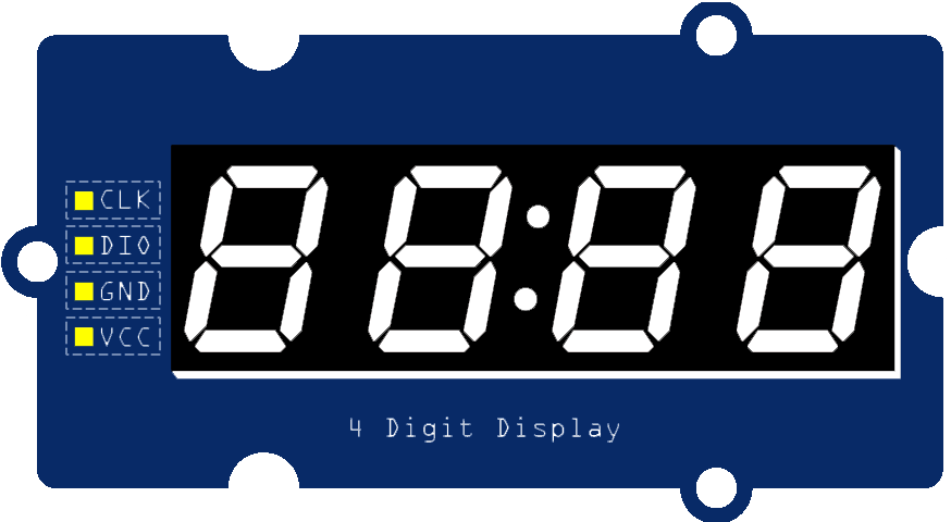
Power Pins
The power pins consist of two pins like all other devices. The first pin is the power (VCC) input pin to give the voltages to the module. The ground (GND) is pin to make the common ground with external devices.
Communication Pins
There are only two communication pins, in which one is a clock pin (CLK) and the second one is a data pin. The Clock pin helps to keep the clock pulse sync in with module and microcontroller/Arduino. The data pin helps in sending and receiving data from the microcontroller/Arduino board.
Grove 4 Digit Display Module Features
- The use of only two pins can control the four combined 7-segments.
- The device is compatible with Arduino boards with the use of a single library.
- Any alphanumeric value can show on the module from the microcontroller.
- The module TM1637 gives the 8 luminance levels which are adjustable through the programming.
- The device operates on both 3.3V and 5V.
Applications
- The module is commonly available in the power display devices.
- In stopwatches and timers, module usage is mostly at the developers’ level.
- The module is also available in Payer timing devices at Masjids.
- The utility power meter also uses to show the data.
Alternative Displays options
16×2 LCD, NOKIA 5510, OLED DISPLAY, ST7920 GLCD, SEVEN SEGMENT DISPLAY
4 Digit Display Module Construction
The construction of the module is simple and its working principle is related to some other modules. Firstly, it has four 7-segments whose data change according to the Arduino/microcontroller output. In the module each 7-segments has eight pins, seven pins are the anode pins of the 7-segment and the remaining one pin is the common ground pin. All 7-segments come up with a total of 32 pins in total. In the module, a driver helps to use all the 4-modules with only 12 pins and then it takes the data for all the 12 pins with its two input pins. The module uses the below circuit to work with the 7-segment.
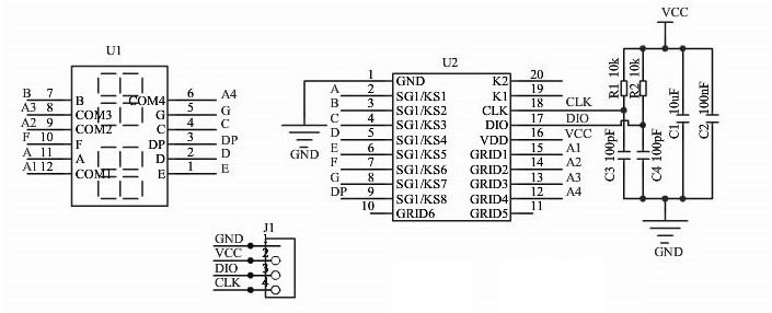
Driver
In the diagram, SG1 pins relate to the input of every 7-segment and DP commonly. The GRID pins are connected individually with the common ground of the 7-segment. The driver controls all 7-segment and intensity of light with these 12 pins only. The principal driver is using here is from the matrix module. The module operates each 7-segment too quickly with these 12-pin that their differentiate is undetectable by a human eye. The drive first changes/shows the data on the first 7-segments, then second and so on. The process keeps happening until new data appear on the input DIO pin on the module by the microcontroller/Arduino. The driver also has some hardware requirements to operate which can clear from the above image.
How to use TM1637 Grove 4 Digit Display Module?
The module is very common in industrial and commercial applications. The use of the module isn’t only due to its clear display and small size only. It is due to its usage with multiple devices by simple programming. There are a bunch of libraries with which the module is controllable but for the Arduino is:
#include "TM1637.h"
The above library just uses the simple and easiest command to operate the device. It is compatible with all types of Arduino boards. After initializing the library needs to know the PIN of the Arduino board where the clock and Data pin is connected. To use the module, use the following command to declare the Arduino Pins:
TM1637 tm1637(CLK,DIO);
The above command will declare the pins of the Arduino for the module. Replace the CLK from the instruction with the PIN of the Arduino where module CLK pin connects. Then replace the DIO with the Arduino pin where DIO of the module connects. After that, the hardware initialization completes but the display of data will require some further programming with the above library.
Initialization
In the module, the library won’t work until it is initialized in the Arduino setup. To use the module, use the following command to initialize the module in the Arduino setup:
tm1637.init();
The above command will initialize the use of the library for the module in the Arduino. In the initialization, the tm1637 is a variable we are using from the pin initialization part and it is changeable too. “Here we are using the tm1637 so we will continue further detail with this variable as a reference”.
Intensity Control
In the programming, the intensity of the 7-segment is also controllable. To control the intensity the following command will help. It is just a single line command which controls the intensity of all the 7-segments at a time.
tm1637.set(0);
The above command will make the 7-segment bright darkest. To change the intensity, change its value from 0 to 7. They will give the BRIGHTEST output at 7. The following numeric values are also replaceable with the variables.
BRIGHT_TYPICAL = 2
BRIGHT_DARKEST = 0
BRIGHTEST = 7
The above variable/alphabetic data has a predefined numeric value. It is also useable to set the intensity with intensity set command.
Data Display
The data on each 7-segment is controllable individually. To show the data on every 7-segment use the following commands:
tm1637.display(0,DATA);
tm1637.display(1,DATA);
tm1637.display(2,DATA);
tm1637.display(3,DATA);
The above command will show the data on the module but the first numeric values 0,1,2,3 describes each 7-segment of the module. In the case of undeclaration of each segment, the module will show the dummy data on the module. Then the second part is the DATA part, it needs to replace with the number value. The total 0-9 numbers are shown able but incase of 10-15 decimal the value will be in alphabetical form. The data for 10-15 will be A, b, C, d, E, F. The ratio sign on the module will blink whenever the Arduino uses the display commands. If a single command is being used for single 7-segment then the ratio signs LEDs will blink.
Example of Arduino Interfacing
The module is easy to interface and easy to use. It is useable with almost every Arduino board no matter the size is. To use the board, the following circuit will help.
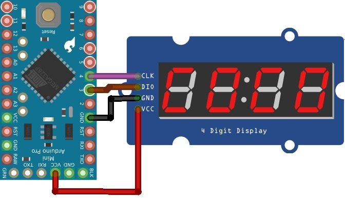
The above circuit is only for Arduino Mini Pro and its communication pins are changeable according to the other Arduino boards. The following given code will show all the 0-15 digits value on the module:
#include "TM1637.h"
TM1637 tmDis(4, 3);
void setup()
{
tmDis.init();
tmDis.set(2);
}
void loop()
{
int8_t numTab[] = {0,1,2,3,4,5,6,7,8,9,10,11,12,13,14,15};  //0~9,A,b,C,d,E,F
int8_t listDisp[4];
unsigned char i = 0;
unsigned char count = 0;
delay(150);
while(1)
{
i = count;
count ++;
if(count == sizeof(numTab)) count = 0;
for(unsigned char BitSelect = 0;BitSelect < 4;BitSelect ++)
{
listDisp[BitSelect] = numTab[i];
i ++;
if(i == sizeof(numTab)) i = 0;
}
tmDis.display(0,listDisp[0]);
tmDis.display(1,listDisp[1]);
tmDis.display(2,listDisp[2]);
tmDis.display(3,listDisp[3]);
delay(500);
}
}
2D Diagram

How can I extend this ic to big and diy seven segment with a different voltage and current