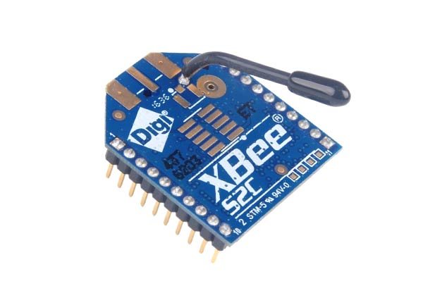
XBee S2C RF Module offers secure network-based wireless communication. In XBee S2C communication the device transfers the data with 2.4GHz speed. This module can only communicate with other modules. The communication method of the module is like creating a network then communicate with each other for data transmission. The data only transfer from XBee to XBee; therefore, it doesn’t matter which company design the XBee module. The only matters are the availability of the XBee S2C mesh network. The preference of the module is due to its simple usage method with every corresponding module-based network. It most uses for peer to peer communication.
Xbee S2C Module Pinout Diagram
The XBee is a distinct kind of RF module from others. Firstly, it offers multiple communication methods, which almost cover every microcontroller and board with it. Additionally, it has some GPIO pins which are useable directly with the XBee module. Although, this RF module doesn’t require any Arduino or Microcontroller to operate. Its own IDE can make it a stand-alone device. But we can interface it with microcontrollers quickly through UART pins.

Pin Configuration Details
LEFT SIDE PINS
| PINS | DETAIL | |
|---|---|---|
| 1 | VCC | To Power input to the device. |
| 2 | DOUT/DIO13 | It acts as a UART serial input
It also acts as a GPIO pin. |
| 3 | DIN/CONFIG/DIO14 | It acts as a UART serial data input.
It also works as a GPIO pin |
| 4 | DIO12/SPI_MISO | Pin4 is the data output pin for SPI communication.
The pin is also useable for simple GPIO functions. |
| 5 | RESET | This pin will help to reset the device through an external signal. |
| 6 | RSS/PWM0/DIO10 | The pin6 is useable for PWM and GPIO pins but at the same time it is also useable for signal strength indication in UART serial communication |
| 7 | PWM1/DIO11 | This pin act as GPIO and Pulse width modulation. |
| 8 | RESERVED | It’s a no connections pin. |
| 9 | DTR/SLEEP_RQ/DIO8 | This pin controls the sleep line of the module XBee S2C.
It also acts as a GPIO function. |
| 10 | GND | Pin 10 is a ground pin for command ground with external devices like power supply |
RIGHT SIDE PINS
| PINS | DETAILS | |
| 11 | DIO4/SPI_MOSI | This pin acts as a GPIO pin but it can also help in SPI communication for data input of XBee. |
| 12 | CTS/DIO7 | This pin act as an indicator of RS232 communication to clear about the flow control.
This pin also works a GPIO functions |
| 13 | ON_SLEEP/DIO9 | The pin ON_SLEEP helps to check the status of the XBee. It is also useable for GPIO functions. |
| 14 | VREF | The direct interface of ADC VREF is helpful in analog voltage reference. |
| 15 | ASC/DIO5 | This pin is helpful to get the indication of a device that is in sleep mode and diagnostic mode. The pins also work GPIO pins. |
| 16 | RTS/DIO6 | In RS232 communication the RTS requires to indicate the flow control.
This pin also acts as GPIO pins. |
| 17 | AD3/DIO3/SPI_SSEL | This pin is a slave select pin of SPI communication.
It also works as GPIO and Analog data input pin. |
| 18 | AD2/DIO2/SPI_CLK | The pin 18 is a clock pin of the SPI communication. This pin also works in Analog input and GPIO too. |
| 19 | AD1/DIO1/SPI_ATTN | SPI_ATTN pin helps to get the attention of the master whenever there a data output from XBee.
This pin also works as GPIO and Analog input. |
| 20 | AD0/DIO0/CMSN BTN | The pin20 is for the Commissioning button.
it is also useable for GPIO and ADC input. |
XBee S2C RF Module Features
- The device can act as a stand-alone device
- It can communicate up to 400ft in the closed area but in line to line sight, it can communicate up to 4000ft without any interference.
- The module act as a mesh network with each other.
- It uses a frequency range of 2.4-2.5GHz and has 16 sequences of channels.
- The microcontroller can send the data up to 256kbs at UART communication but the data send rate can extend up to 5Mbs by SPI communication.
- The device works with 3.3V and uses only 40-45mA current at maximum usage.
- The XBee has an ESD protection of 3000V.
- The device is controllable and programmable by a single software that is official.
- The Data rate of the module is up to 250,000bps.
XBee S2C Applications
- The device is suitable in-home automation, it can create a mesh network which makes it safe.
- For every medium-range communication, the device is reliable.
- For smart communication, the module XBee S2C is a better choice as compared to the other modules.
How to use XBee S2C?
The XBee is easy to use and it will always in the shape of a network. A single XBee has no use. To use the XBee two modules are necessary. First, understand how the network of XBee works. A single XBee can work on three types of functions. All of them are:
Coordinator/Manager
A complete XBee network requires a coordinator to operate. The coordinator will work on assigning and managing some protocols and functions in the network.
- It will be responsible for synchronization of the nodes between the network
- Every channel and PAN ID (Example: like an IP Address) will assign by the Coordinator.
- It will be responsible for the joining of the network and router.
- The basic function of the coordinator is acting as a bridge and deliver the data from one end to the other.
Router
The router is the second part of the network. Even in every kind of network, there is a router. The basic function of the router is:
- To deliver the data from one network to the other.
- Creates a bridge between networks
- To establish the path between node to node within and outside the network.
End Device
The end device is like a child to the network. In the network, the Coordinator/Manager and router act as a parent. Everything is done by the router and coordinator. The only function of the End devices is to operate as receiving and send data devices. That is the reason sometimes the device goes into sleep mode to save more power.
PAN ID
It is the unique Id given to each device so they can communicate with each other with knowing the incoming and outgoing. The device must have a PAN ID of the network which it is going to join. After getting the ID they only need a channel to communicate. The router and Coordinator allow the other devices to join the networks according to the PAN ID.
Channel
There is a total of 16 channel and each channel is useable by a single END DEVICE. The coordinator can decide between the channel and PAN ID. It can decide which channel and PAN ID to use. The number channels very between XBee to XBee. Some modern version has two but some have 16 which is the maximum number of channels till now in XBee S2C.
XBee S2C Programming software
The XBee is designed by a Digi company which also gives software to set up the device. To use the XBee the devices should setup first otherwise the network can’t decide and perform its operations. To set up the module there are a bunch of graphic methods and commands which can be view in the datasheet.
Xbee S2C Interfacing with Microcontrollers/Arduino
The XBee is interfaceable with other devices using serial and SPI pin. Take an Arduino as an Example. In Arduino just connect the module with the device through DIN and DOUT pins then send and receive the data using the following command. This is a simplistic connection diagram of the S2C – RF Module with Arduino.

Programming with Arduino IDE
To program this device with Arduino, we need UART communication pins of Arduino to send and receive data from Xbee.
Serial.print("DATA"); // For sending
Serial.read(); //For receiving
Every microcontroller and Board can communicate simplicity through the module. The only thing should keep in mind about the baud rate. The baud rate for UART communication needs to be set for XBee through serial communication. You can read this complete tutorial:
Projects
- Remote Monitoring System with Labview and XBee
- Accelerometer Based Hand Gesture Controlled Robot using Xbee
Xbee Modes of Operation
The XBee offers two modes in transferring data. The first mode is the AT command mode and the second is API mode. The AT command mode takes the data from the input and transmit as it is received by the microcontroller. In API mode the method is different. The data first converted into the frame and transmit. The frame consists of multiple sets which make the communication much secure than before.
The device has a lot of more advanced features which are helpful in most of the communication method. These above are the general methods and are initial methods for simple communication and to establish a network.
2D Diagram

Other Wireless Modules
Please verify the pinout diagram shown. It says that both the 2nd and 3rd pins are serial input pins. The 2nd pin should be the output pin.