Automatic power source selector circuit using Arduino: Hi Eveyrone, I hope you are fine and doing well. This project is about automatic power source selection circuit diagram using Arduino. I have already posted a article on automatic transfer switch using pic microcontroller. The basic objective of this project is to select power supply form two different sources. Two power sources like main grid and solar power is used in this project. When both sources are available we want to feed the load from main grid. When power from main grid is not available, we want to feed the load from solar power. We are considering output of solar inverter in this embedded system project. In this automatic power source selection project we have used Arduino to switch between two power sources. Arduino is used to measure ac voltage of main grid and output of solar inverter. According to availability of power sources Arduino take action and turn on and turn off respective relay.
block diagram of automatic power source selection
Block diagram is of this project is given below. As you can on the top left side of block diagram is a solar inveter. Output voltage is measured by Arduino which is given at the top center of the block diagram. On the top right side of block diagram is power from main grid. Output voltage is also measured with Arduino. Relay driver module is interface with Arduino to switch between two power sources.

Automatic power source selector working
Analog to digital converter of Arduino is used to measure analog voltage. Arduino can not measure ac voltage directly. So We have used a step down transfer to step down voltage from 220 volt AC to 6V AVC. After that I a rectifier circuit is used to convert negative half cycle of sine wave to positive half cycle. Because Arduino can not measure negative voltage and reference voltage for Arduino is zero volt which is ground. So we have use full wave rectifier to convert negative half cycle into positive half cycle. After rectifier a voltage divider is used to further step down voltage. Why we need to used voltage divider circuit? Because output of full wave rectifier is 8 volt peak to peak and Arduino can measure maximum 5 volt. So we used voltage divider to further step down voltage below 5 volt.
I have posted a article on ac voltage measurement using microcontroller. I have explained everything in very detail in this article. I recommend you to read this article first to get understand of code and how we further develop code alternating voltage detection. Arduino measures voltage of both main grid ans solar inveter. A relay driver module is interfaced with Arduino to transfer load from one power source to another power source. You should have a concept of LED blinking with arduino to use digital output pins of Arduino. Relay driver is interfaced with Arduino using digital output pins of Arduino. you can read this article on relay interfacing circuit to know more about relay interfacing.
Circuit diagram of Automatic power source selector
Circuit diagram of automatic power source selector is given below. I have already explained you all the components and working of this project. So rest of circuit diagram is simple and you can easily understand it. Here LCD is interfaced with Arduino. It is used to display voltage of both solar and main grid. 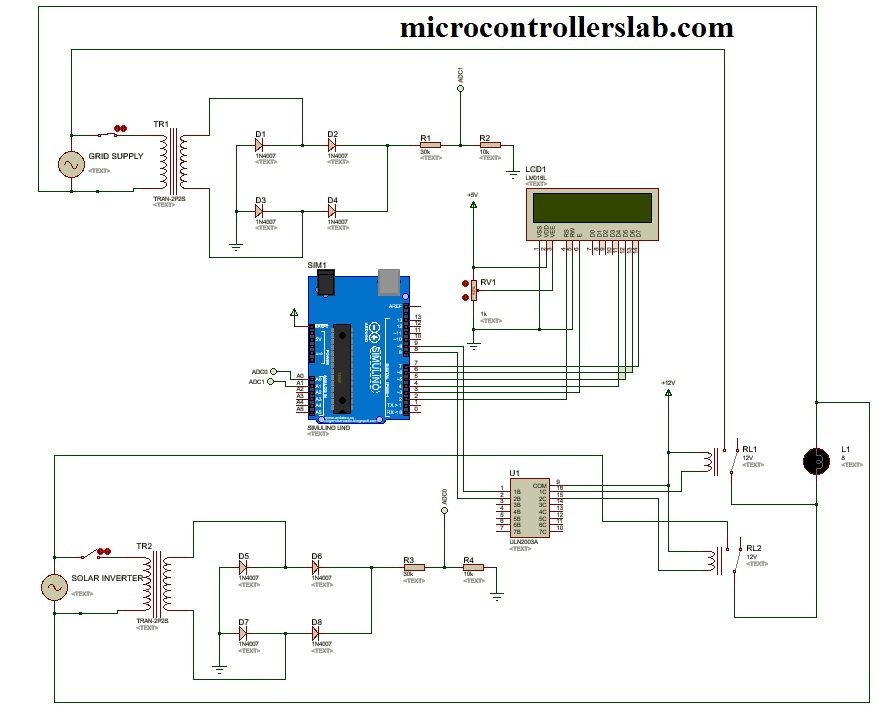
Video of simulation
Interested in purchasing code ? Contact me at microcontrollerslabhub@gmail.com
merci beaucoup c’est très intéressant Mr BILAL
i need this project
I need also this project, Can you please help me make this?
Thank you! Very well detailed!
Can you plz give me the source code for this project,, it will be very helpful for me
how to work
i need to to this project
Can you plz give me the code for this project, it will be very helpful for me
nice project, please can i get the source code
can I please buy the source code?
achacynthia212@gmail.com
Thank you
Nice work!! It would be better if you share the code file and other documentations. Thanks!
Nice work!! It would be better if you share the code file and other documentations.
please give me Arduino code for this simulation
Please give me the arduino code for my project
Please give me the arduino code for my project
SIMPLIFIED CIRCUIT DIAGRAM. SO LOVELY.
Please for the list of materials