LED Blinking using PIC Microcontroller with examples: In this tutorial, we will see examples to interface an LED with PIC Microcontroller. LED blinking is the simplest and most commonly used example for the beginners. It acts as a stepping stone for microcontroller development. It gives the basic idea of working with the controllers in a practical environment. In this LED blinking tutorial, you will learn how to use input and output ports of PIC microcontroller with MPLAB XC8 Compiler and MikroC Pro.
PIC Microcontroller LED vs Push-button use
For example, when we want to drive an external device such as an LED with Pic microcontroller, the GPIO will be used as a digital output pin. Similarly, when we want to sense an external signal such as push-button, switch, digital signals with pic microcontroller, the GPIO pins will be used as a digital output pin. For example when we use keypad interfacing with a microcontroller or we use a switch with a microcontroller we use pins as input.
LED Interfacing with PIC Microcontroller
Before we see how to interface an LED with pic microcontroller, we need to understand some basics of a light-emitting diode such as its current and voltage requirements. How much does it require to turn it on? What is the forward voltage rating of an LED?
LED Introduction
It consists of two terminals namely anode (+) and a cathode (-). As its name suggests, it is a light source that emits light when we apply a voltage across its terminal. We usually use it as an indication signal in embedded systems projects. For example, it is used to indicate either power is applied to the circuit or not. Some other applications are:
- LED Flasher
- Sequencer
- Battery Level Indicators
- Back-up lights
- Traffic lights and Many others
LED Terminals
This picture shows an electronic symbol and a physical diagram of light-emitting diodes. As you can depict from the diagram that it consists of two-terminal such as anode and cathode. An anode is a positive terminal and we connect positive terminal of power supply to this terminal. Similarly, we connect the negative terminal with the cathode.
While using an actual LED, we can find cathode and anode terminal in two ways.
- The longer lead always an anode terminal and shorter one is a cathode
- Secondly, we can identify cathode from the flat surface and another one will anode leg
LED Current and Voltage Requirement
Before interfacing LED with Pic microcontroller, we should find its forward current and forward voltage. The intensity of lights that emits from it depends on the forward current. Greater the forward, the higher will be light intensity. But every device has a peak forward current and voltage. It cannot withstand the current and voltage greater than the peak value.
For example, if we use a RED_LED that has a brightness of 5MCD, it will operate at 10mA current.
Note: millicandela is a light intensity unit that is used to measure light brightness.
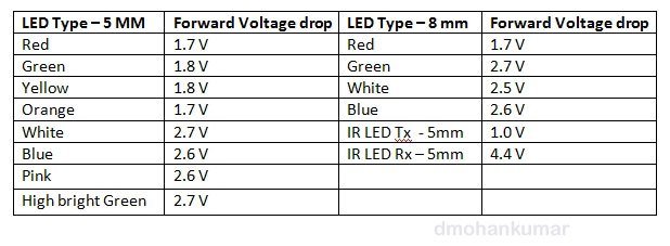
The forward voltage depends on the color and size of an LED. This table shows the forward voltage drop of different color LEDs according to color and size.
Therefore, we can conclude from the above table that the average forward voltage drop is about 2V. The typical forward current is about 10mA. But, there are a small size (1MM) LEDs also available in the market that can operate even at 1mA. But you should select the device according to your brightness requirement.
LED Connection with PIC Microcontroller
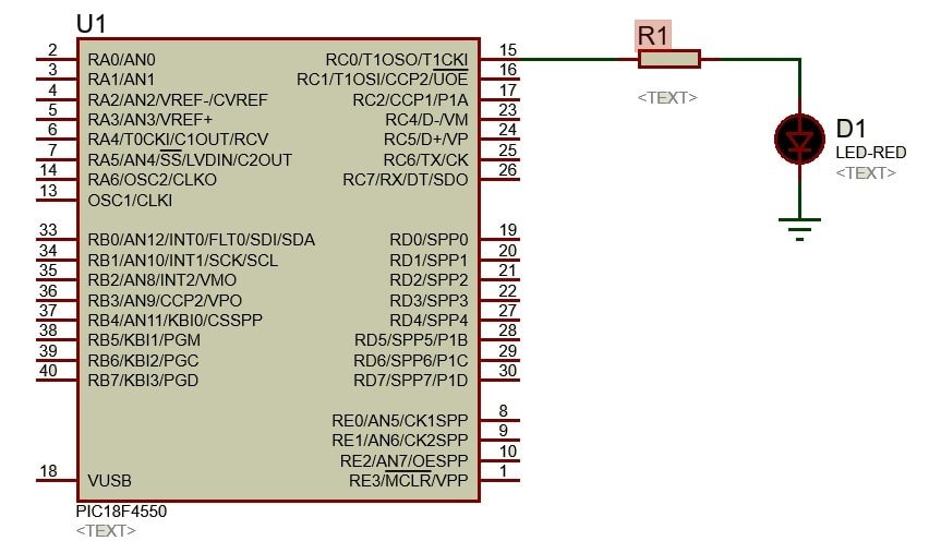
Last but not the least, this section lists all details on how to interface an LED with a pic microcontroller. First, let’s assume that if we use any pin of pic microcontroller as a digital output pin, it can provide +5 volts at the output. This diagram shows a connection diagram/LED interfacing with pic microcontroller.
Let’s assume that the forward current is 10mA. But you can always find a peak forward current value from the datasheet. We can easily calculate the current limiting resistor value (R1) by using this equation:
R1 = 5 - 2 / 10mA
R1 = 3/10mA = 0.3K = 300Ω
We can easily find a resistor value close to 300Ω in the market.
Why Do We Need A Current limiting Resistor?
You must be thinking why do we need to use a resistor while interfacing an LED with Pic microcontroller? This is because of the current limit of GPIO pins of Pic microcontroller. According to the PIC18F4550 microcontroller datasheet, the maximum current a single pin can provide up to 25mA. Another reseason is because of the peak forward current of the light-emitting device.
LED Blinking using MPLAB XC8 Compiler
In this section, we will see an LED blinking example with MPLAB XC8 compiler. But before that, you should know how to use MPLAB XC8 compiler, we recommend you to read this post first:
After watching this video and reading the above article, you should know how to create a new project with MPLAB XC8 and how to set configuration bits of any Pic microcontroller ( PIC18F4550). In this example, we use the PIC18F4550 microcontroller for LED controlling demonstration.
LED Blinking with PIC18F4450 Circuit
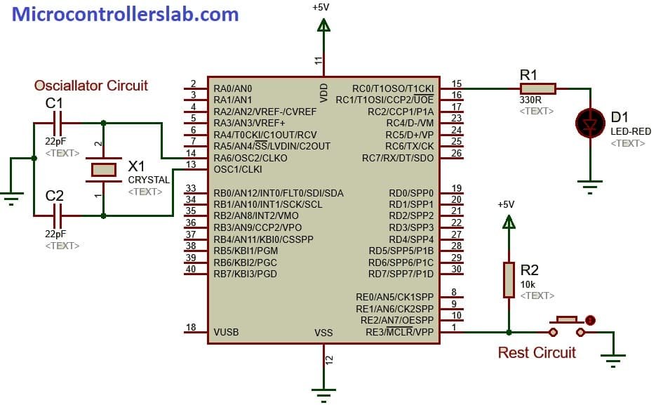
This circuit shows a connection diagram of PIC18F4550 with an LED. We connect LED-RED with PORTC pin RC0 through a current limiting resistor R1 (330Ω).
Now let’s see an LED blinking code in MPLAB XC8 compiler. Like every PORT of PIC18F4550, PORTC is also a 7-bit bidirectional port. Each pin can be used both as a digital input or a digital output. These three registers are associated with PORTC:
TRISC – Data Direction Register
As its name suggests, this 7-bit register is used to set the direction of data. In other words, it defines the nature of pin either as a digital input or a digital output. If we set TRISC all bits to 1, it configures all pins as a digital input and similarly setting “TRISC=0x00”, configures all pins as a digital output. In MPLAB XC8, we can define them like this:
TRISC=0x00;   // set all PORTC bits output
TRISC=0xFF;   // set all PORTC bits input
We can also access individual bits of TRISC register in MPLAB ana configure some pins as input and some as an output.
TRISC0 = 0;  // set RCO pin as a output
TRISC1 = 0; //  set RC1 pin as a output
LATC – Data Latch Register
The Data Latch register (LATC) is also memory mapped with PORTC. Every read-modify-write operations we perform on the LATC, it latches the value on PORTC.
PORTC
PIC18F4450 microcontroller PORTC is a multi-function port. All pins are shared with other modules such as ESUART, USB, I2C, and SPI communication modules, expect RC4 and RC5 pins.
Note: RC4 and RC5 pins can be used only as digital input pins only. Because internally there are not TRISC bits associated with them.
LED Blinking Code MPLAB XC8 Compiler
This code blinks an LED with a delay of one second. __delay_ms() function used to define a delay in milliseconds.
#include <xc.h>
#define _XTAL_FREQ 20000000 //define crystal frequency to 20MHz

void main(void)
{
TRISC0=0; //set RC0 pin as a digital output pin
while(1)
{
   RC0 = 1;                  // set RC0 pin to logic High &  turn on
   __delay_ms(1000);  //add delay of 1 second
   RC0 = 0;                  // set RC0 pin to logic low & turn off
  __delay_ms(1000);  //add delay of 1 second

}
return;
}
We can also interface multi-color or RGB devices with pic microcontroller. Read this post:
LED Sequencer Circuit using Pic Microcontroller
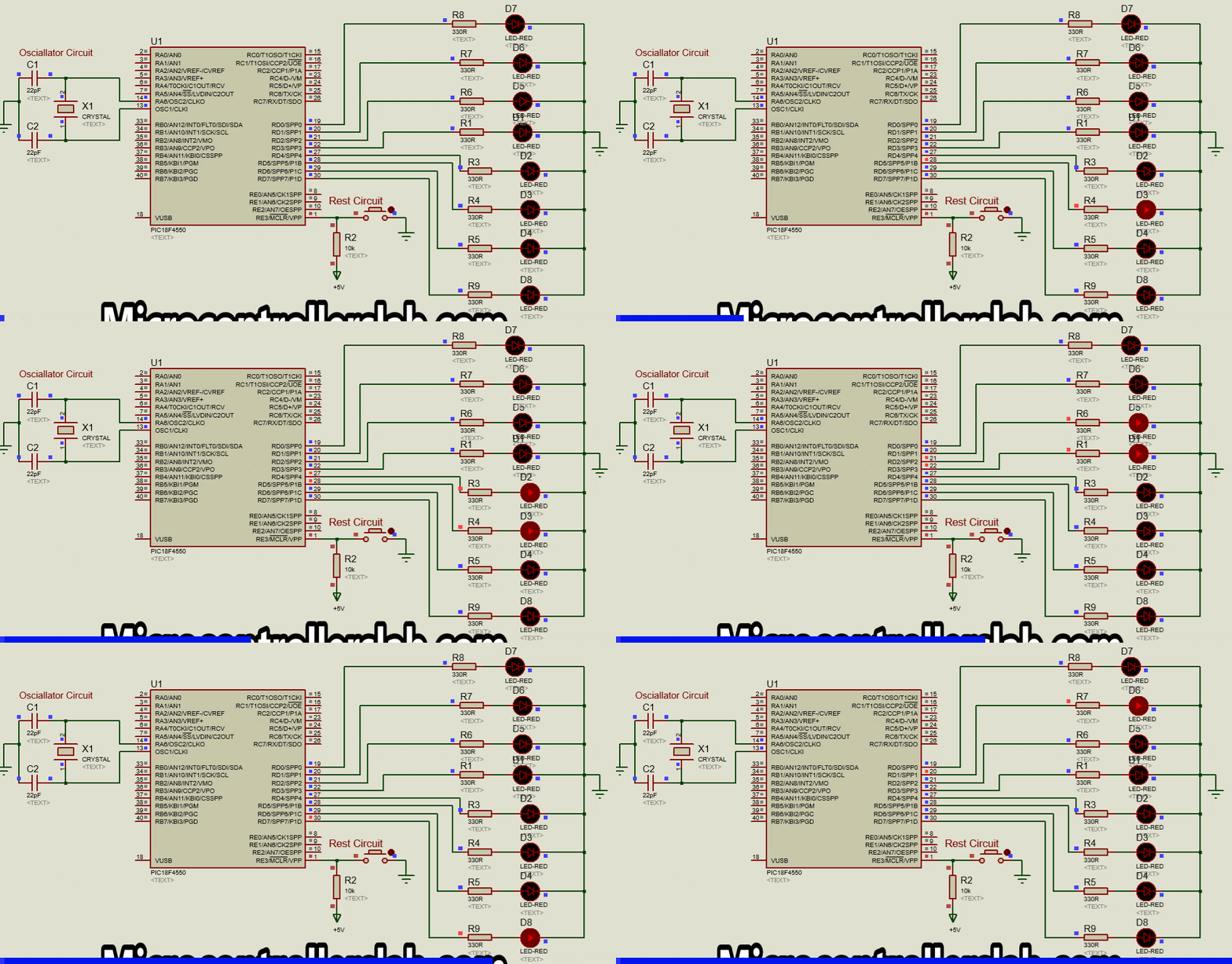
This section describes a LED sequencer circuit designed using a pic microcontroller. The sequencer circuit generates a blinking pattern sequence with a specified pattern. As you can see in this circuit, it blinks alternate LEDs with a sequence of one, two and three respectively.
In this circuit, we use PORTD and eight light-emitting diodes are connected with this PORT through current limiting resistors. This is a complete code in MPLAB XC8 compiler.
#include <xc.h>
#define _XTAL_FREQ 20000000 //define crystal frequency to 20MHz

void led_sequence(char get)
{

{
for (int j=0; j<=7; j++)
{
PORTD = get << j; //LED move Left Sequence
__delay_ms(200);
}
for (int j=7; j>=0; j--)
{
PORTD = get << j; //LED move Left Sequence
__delay_ms(200);
}
}
}

void main(void)
{
TRISD=0; //set PORTD as a digital output PORT
while(1)
{

led_sequence(1);  // sends 00000001 to sequence function
led_sequence(3);  // pass value 00000011
led_sequence(7);  // pass value 00000111

}
return;
}
Now let’s see the working of code. First of all, led_sequence(char get) function used to right shift and left shift values passes to this function as an argument. First ‘for loop’, sends the value to PORTD eight times with the delay of 200 milliseconds. After every repetition of the ‘for’ loop, it also left shift data by one bit. Similarly, second ‘for’ loop, send data to PORTD seven-times by shifting data one bit toward right.
void led_sequence(char get)
{

// this loop executes seven times and every time left sift data by one bit
for (int j=0; j<=7; j++)
{
PORTD = get << j; //left shift data
__delay_ms(200);
}
// this loop executes seven times and every time right sift data by one bit
for (int j=7; j>=0; j--)
{
PORTD = get << j; //right shift data
__delay_ms(200);
}

}
These lines send value to the sequence function.
led_sequence(1); // sends 00000001 to sequence function
led_sequence(3); // pass value 00000011
led_sequence(7); // pass value 00000111
LED Blinking Example MikroC Pro
In this section, we explain how to interface an LED with a pic microcontroller and programming using MikroC Pro for pic compiler.
LED blinking circuit diagram
For this example, we will demonstrate the working of an LED Blinking circuit using the PIC16F877A microcontroller. The circuit diagram and the simulation will be done in Proteus. The following circuit diagram shows we have connected LED with pin number one of PORTC. A resistor is used as a current limiting resistor. Because the maximum current a single pin can provide to LED is 5mA.
- Connect RC1 pin of PIC16F877A microcontroller with an LED through a resistor
- Select the PIC16F877A microcontroller and rest of the components as well from the Proteus built-in libraries as shown in the circuit diagram below.
- The LED is connected to pin RC1 of PortC via a 330R resistor R1.
- For oscillation, connect a 4MHz crystal across pin13 and pin14 of the microcontroller with 2 capacitors C1 and C2 on either side of the crystal.
- Connect a pull-up resistor R2 on the MCLR pin of the controller, the other end of which will be tied to Vdd.
How to use GPIO Pins of PIC16F877A
LED Blinking Code MikroC Pro
To simulate the circuit as per our desired function i.e. for the LED to blink, the microcontroller PIC16F877A needs to be programmed with a relevant C-code. Write the following LED Blinking code in the mikroC compiler. If you don’t have experience with MikroC pro, you can read this post:
- How to Use “MikroC PRO for PIC” to Program PIC Microcontrollers
- Pic microcontroller programming in c using Mikroc Pro for PIC
void main()
 {
TRISC = 0x00; //configuring PORTC as output
 //Loop executed infinite times
while(1)
 {
PORTC=0b00000010; //Pin1 of PORTC high
delay_ms(1000); //Delay of 1 sec
PORTC=0b00000000; //Pin1 of PORTC low
delay_ms(1000); //Delay of 1 sec

}

}
LED blinking Code Description
The while loop will execute infinite times. The LED connected to pin RC1 of PORTC will keep on blinking with a 1-second delay (1s=1000ms).TRISC in instruction 2 configures PORTC as an output port. Pin1 of PORTC is set to 1 (HIGH) in instruction 4 and after a delay of 1000ms, it is set to 0 (LOW) in instruction 6. This process is repeated until the program is aborted. This causes the blinking of the LED. The speed of the Blinking LED can be increased or decreased by varying the delay value.
The lines written next to the instruction after a “//” character, are the comment lines. These lines are not compiled with the program, instead, they are used to explain the operation of the programming statement. For longer comments, start the sentence with the character “/*” and end with the character “*/”.
Simulation Result
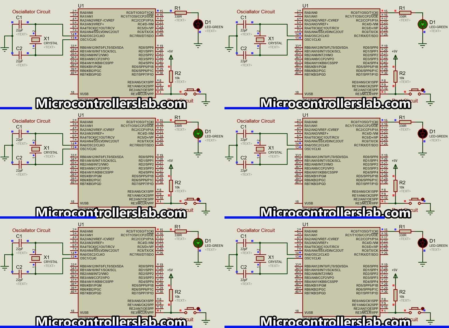
Result of LED blinking code using PIC microcontroller:

Applications
There are several applications of blinking or flashing light. A flashing emergency LED light is used for capturing the attention of the masses as it makes people look up and pay attention to more consideration. Also, the devices installed on telecom sites, use a blinking LED to ensure that the communication is in progress.

I have added 1 second delay but still led not glowing.advice me next
check your microcontroller and LED, It might not program properly.
Microcontroller shows input voltage of 7v at pin 1 , but at pin 16 where led is attached it shows 1.42v .
how it can be verified that either code is burn in microcontroller or not??
LED is verified it glows when just provided supply..
Microcontroller shows voltage 7v at pin1 while pin 16 where led is attached shows voltage of 1.42v.
how it can be verified that either code is burn i controller or not??
LED is checked and verified it glows when just supply it source.
Microcontroller shows voltage of 7v at pin1 but pi 16 at which led is attached it shows voltage 1.42 voltage.
How it can be verified that either code is burn in controller or not?? as I am doing led interface just to check whether code bur or not..
LED is verified because it glows just when provided supply.
Need to knw more abt mickro C compiler
Dear Malik
I can use a variable resistor for change the delay time on led blinking, please help. Thank you
1. void main() {
2. TRISC = 0x00; //configuring PORTC as output
3. while(1) { //Loop executed infinite times
4. PORTC=0b00000010; //Pin1 of PORTC high
5. delay_ms(1000); //Delay of 1 sec
6. PORTC=0b00000000; //Pin1 of PORTC low
7. delay_ms(1000); //Delay of 1 sec
8. }
9. }
I am bigginer using pic16f877a how to start lerning this controller
How to write 5 times led will be glow after led will be 0
how to i get sequence like
0000 0001
0000 0011
0000 0111
0000 1111
0001 1111
0011 1111
0111 1111
1111 1111
In led_sequence(number) pass the equivalent decimal value. For instance, led_sequence(15) for 00001111
//initial PORTB=0x00;
for(i=0;i<=7;i++)
{
PORTB=( (0x01) | (PORTB <<i) ) ;
}
write a MikroC program to blink a LED will a delay subroutine
Apply C programming to perform running light operations in 2 seconds using the given simple loop. Where only one LED will light up at a time. The LED is connected to PORT C.