PIR sensor interfacing with pic microcontroller, In tutorial you will learn how to interface by sensor with pic microcontroller. it will be a step by step guide for how to make a Motion detector circuit using PIR sensor and pic microcontroller. Pir sensor has many applications like motion detection burglar alarm and many other applications. I have already posted an article on PIR sensor interfacing with arduino and I have also design a project using Pir sensor and pic microcontroller and project is home security system and have also connected GSM in that project. so in home security system we are detecting motion and then we are sending a message to the owner that we have detected a motion. but in this article we will see how we can connect a pir sensor with pic microcontroller and how we can detect a motion. so let’s start with basic introduction to be IR sensor and what is PIR sensor and how PIR sensor works.
What is PIR sensor?
There are many PIR sensors available in market but we are using passive PIR motion sensor in this project. It can detect a human motion within a range of 10m very easily.PIN out of PIR sensor is shown below. Picture of PIR sensor is shown below It has three pins and function of each pin is described below:
- GND: It is a ground pin and you should connect it with ground of your power supply
- VDD: it is a power supplier pin and it should connect 5 volt of your power supply with this pin
- Output: it is a output pin of the PIR sensor. basically we get output from this pin. I will explain in the later part of this article about function of this output pin and and how output changes at the output of PIR sensor
NoW let’s check the working of PIR sensor and how its works?
PIR sensor working
As I mentioned earlier Pir sensor is a low-cost Motion Detector sensor. it is a passive motion sensors that’s means it can only detect something around it and it cannot transmit anything. Whenever there is a motion around here sensors, it will detect the heat of human body and produces a high output logic 1 at the output of sensor. Every object emits infrared rays when they are heated and on the same principle human body emits IR rays due to body heat. So whenever motion sensor detects human body around it, its output becomes high. we can also adjust the sensitivity of this sensor by changing the variable resistors available on the sensor. One variable resistor is for sensitivity adjustment of distance and other variable resistor is for sensitivity adjustment of time that is the amount of time for which the output should be high.
Required components
We need following components for this project:
- PIR sensor
- PIC16F877A microcontroller
- 16 X 2 LCD
- Buzzer
- Pic kit 3
- Crystal
- 22 pF two capacitors
- 10k ohm resistor
How to interface PIR sensor with pic microcontroller?
To interface PIR sensor with pic microcontroller, you should first know how to use input output ports of pic microcontroller. Because whenever output of sensor becomes high, we need to read this output with the help of microcontroller. I am using pic16f877a microcontroller in this tutorial. It has many input and output ports. So we need to one of the input of pic16f877a microcontroller. So that we can read the logic high output of motion sensor. So first we all we will define digital I/O port of PIC16F877A microcontroller as a input using direction control register that is TRISB. Lets say if we are using PORTB pin number 1 as a input, we need to define these two line in code:
PORTB.B1=0;
TRISB.B1=1;
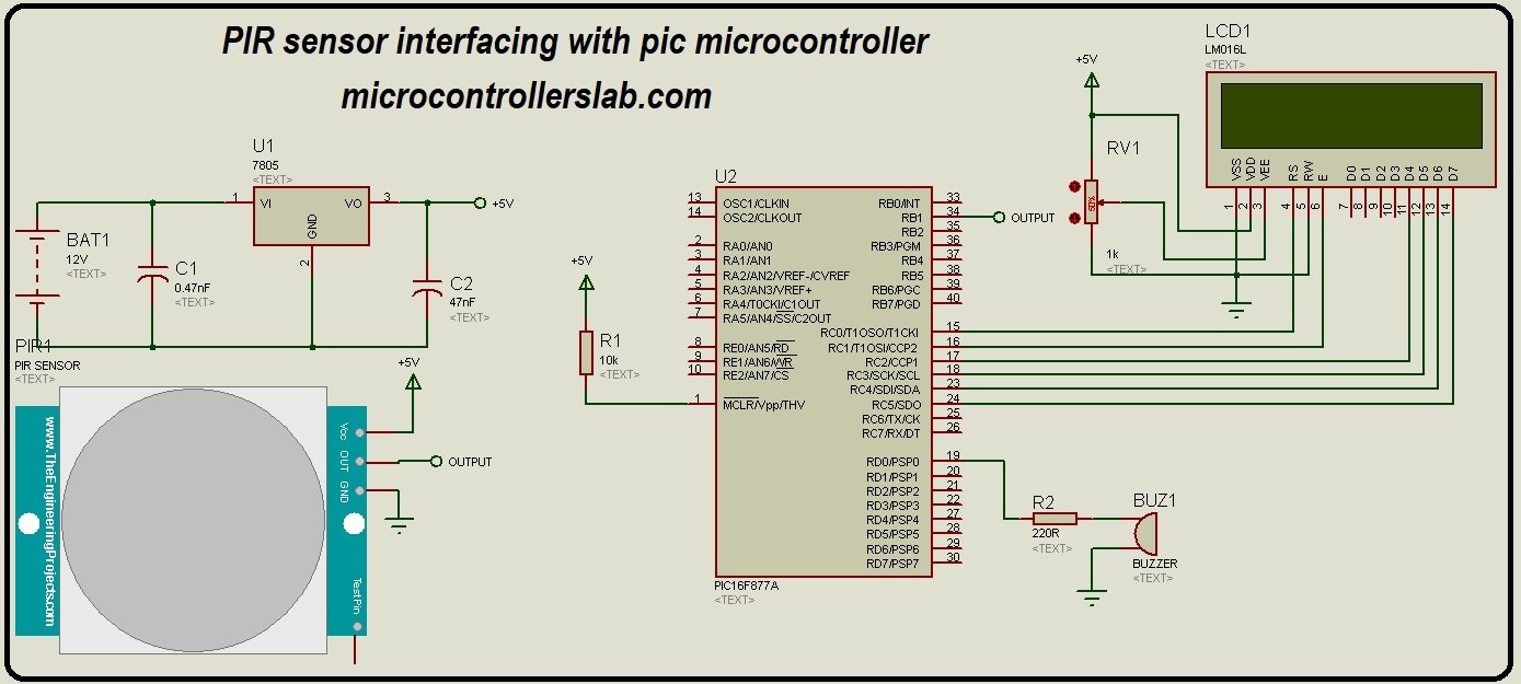
It will declare pin number one of PORTB of pic16f877A microcontroller as an input. So we will connect output of PIR sensor with this pin. You may also like to check a complete tutorial on how to use input/output ports of pic microcontroller. Circuit diagram of PIR sensor interfacing with pic microcontroller is shown below:
LCD is connected with PORTC of pic16F877A microcontroller which will display the message of “ motion detected” and LED is also connected with PORTD pin number 1 which is declare as a output. You can also connect a buzzer instead of a relay if you want to turn on alarm whenever you detect a motion inside room. So there are many adjustments you can make with this embedded systems project according to your requirement. If you don’t know how to interface LCD with pic16f877a microcontroller, you can check this article.
Working as a motion detector:
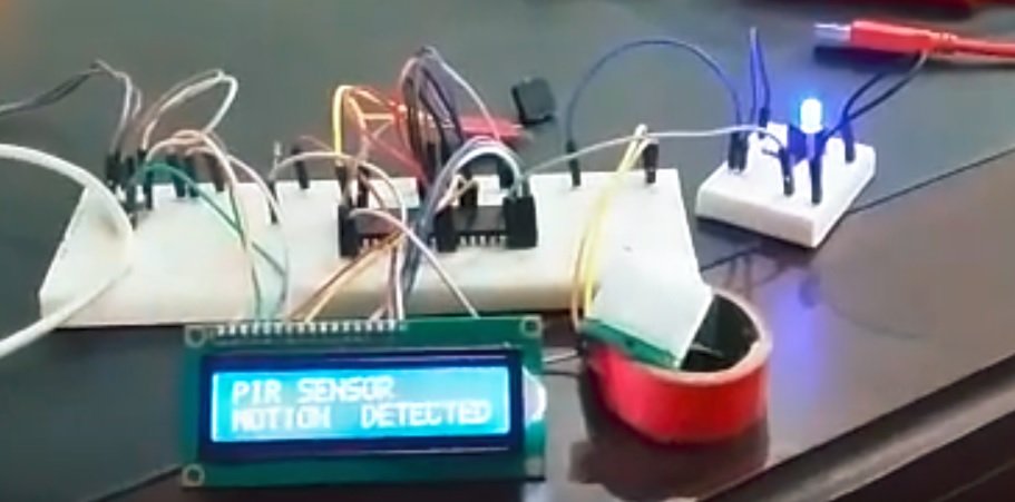
Video below shows the working of PIR sensor being used as a motion detector. When there is no motion inside the room, Led or buzzer will remain off and status will be displayed on LCD that no motion detected. But whenever any motion detected inside the room, LED/Buzzer will become active and LCD also shows the status of motion detection.
Code
Code for this project is written using Mikro C for PIC compiler and you will need a pic kit 3 programmer to upload code your pic microcontroller. so let me explain you code now. In first 6 lines of code we are defining LCD connections with pic microcontroller which is connected with PORTC and after that we have declared some variable. Inside the main loop we are declaring portB pin number 1 as input and PORTD pin number 1 as a output after that we have a while loop. Inside while loop we are repeatedly checking the output of PIR sensor. when the output of Pir sensor becomes high, we will make the LED high and we also update the status on LCD. This is how it works just contact me if you have any issue with the code.
// LCD module connections with PORT C of pic16f877A microcontoller
sbit LCD_RS at RC0_bit;
sbit LCD_EN at RC1_bit;
sbit LCD_D4 at RC2_bit;
sbit LCD_D5 at RC3_bit;
sbit LCD_D6 at RC4_bit;
sbit LCD_D7 at RC5_bit;

sbit LCD_RS_Direction at TRISC0_bit;
sbit LCD_EN_Direction at TRISC1_bit;
sbit LCD_D4_Direction at TRISC2_bit;
sbit LCD_D5_Direction at TRISC3_bit;
sbit LCD_D6_Direction at TRISC4_bit;
sbit LCD_D7_Direction at TRISD5_bit;
//  End of LCD connection setting bits

void main(void)
{

ADC_Init();
 Lcd_Init(); // Initialize LCD
 Lcd_Cmd(_LCD_CLEAR); // Clear display
 Lcd_Cmd(_LCD_CURSOR_OFF); // Cursor off
 Lcd_Out(1,1,"MOTION DETECTOR" ); // Write text in first row
 PORTB.B1=0;  // initially declare it as zero
 TRISB.B1=1; // PIN NUMBER 1 IS DECLARED AS A INPUT
 PORTD.B1=0;  // initially declare it as zero
 TRISD.B1=0; // PIN NUMBER 1 IS DECLARED AS A OUTPUT
while(1)
{ // Endless loop

if( PORTB.B1==1)
{
 PORTD.B1=1;
 Lcd_Out(2,1,"MOTION DETECTED" );
}
else
{
 PORTD.B1=0;
 Lcd_Out(2,1,"MOTION not DETECTED" );
}
}
}
Very good and very easy. I’ve been working around PIR sensor for a while. Can you please explain the function of two jumpers on the sensor? I’m a bit confused abiut them.
Thanks.