In this tutorial, we will learn how to design and simulate a three phase voltage source inverter using Simulink MATLAB. We will explain the workings of inverters, more specifically, 3-phase inverters. Inverters are one of the very basic circuits of electronics, also known as the opposite of rectifiers. At the start, a comprehensive introduction to inverters as well as 3-phase inverters is provided, along with the types of inverters and the effect of their types on the output. After that, the circuit of a 3-phase inverter is implemented in MATLAB’s Simulink. We will also discuss the difference between both types of inverters, i.e., single phase and 3-phase, and compare the output of the block diagram constructed in Simulink. At the end, a basic exercise is provided so that you can solve it on your own, and it will strengthen your knowledge about inverters.
Introduction to Inverters
In electrical engineering, inverters are one of the basic circuits used and are mostly used in UPS (uninterrupted power supply), which is present in almost every house now. Hence, the basic purpose of an inverter is to convert direct current (DC) to alternating current (AC), which is no doubt the opposite of rectifiers. So, for beginners, the definition of AC voltage can be taken as the voltage that changes its direction from positive voltage to negative voltage across the same terminal in a specified period of time over and over again. A simple sinusoidal wave is an AC wave. However, DC can be defined as a constant source of voltage that remains either positive or negative over time.
Types of Inverters
Inverters can be classified into two major types:
- Single phase inverter
- Three phase inverter
Single Phase Inverter
A single phase inverter is the type of inverter in which only one DC source is used, and the output thus formed is a single phase AC waveform. In the circuit, a bridge-like circuit comprised of IGBT transistors is used, which converts DC to AC.
Three Phase Inverter
Alternatively, a three phase inverter uses two input DC sources and 6 IGBT transistors to convert DC voltage into AC voltage, and the output of such a circuit will be a three phase AC waveform with a phase difference of 120. In the explanation below, we will design a three phase inverter in Simulink.
Design Three Phase Inverter using Simulink MATLAB
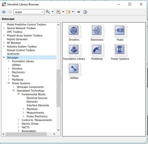
Open MATLAB and then open Simulink using the Simulink icon on MATLAB, as we have been doing in previous tutorials. Create a new blank model and save it in the first hand so we can access it in the future. Now, click on the library browser icon on Simulink’s recently created model. In the library browser, select the section named “Simscape”, as shown in the figure below.
In this section, select the block named power system, as we can see in the figure below.
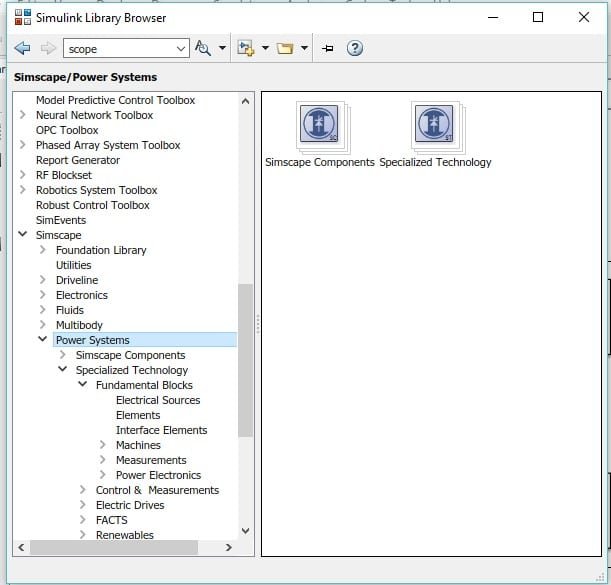
From this section, now select the Specialized Technology subsection. Refer to the figure below.

Now go to the fundamental block present in this section, as shown in the figure below.

Power Electronics
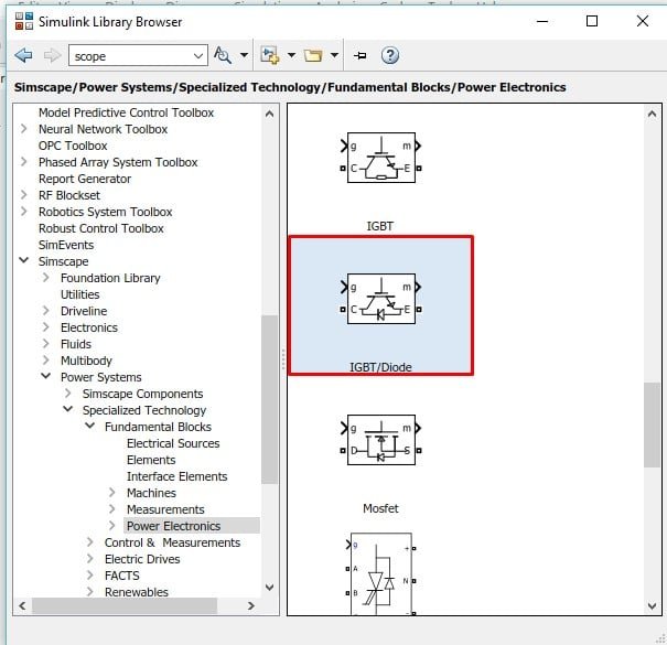
In this section, go to the power electronics block. In this block, all the elements related to power electronics are provided. Refer to the figure below.

In an inverter, as we know, thyristors are used in place of diodes (as in rectifiers). From here, we will select the thyristor block with the name IGBT / Diode as we can see in the figure below.
Three Phase Bridge
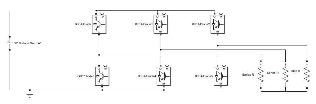
Place six such diodes on the model we created previously and arrange them in three rows with two thyristors each. Connect all of them to make a bridge, as shown in the figure below.

Thus, to access the block properties, double-click on the thyristor block, and in the block parameters dialog box, uncheck the point of showing the measurable port. Refer to the figure below.

In the library browser, go back to the fundamental block section as we have used before and select the block named “powergui” and add it to the model as shown in the figure below.

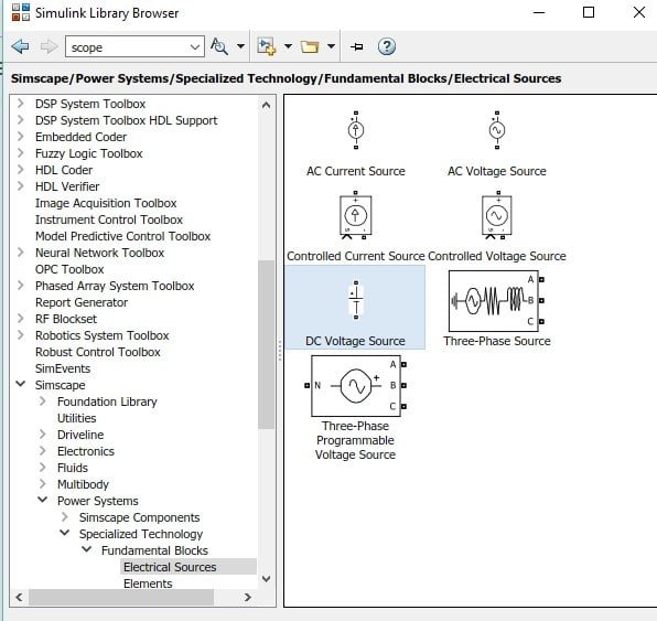
This block contains the definition of all the power blocks used in Simulink and acts like a startup file for the model. Now in the fundamental blocks section, go to the sources section, as shown in the figure below.

DC Source
In this block, select the DC source (input of an inverter) and add it to the model as shown in the figure below.
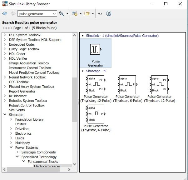
To provide pulses to the thyristor, we also need to place pulse generators on the model. In the library browser, search for the pulse generator in the search bar and add the pulse generator to the model as shown in the figure below.
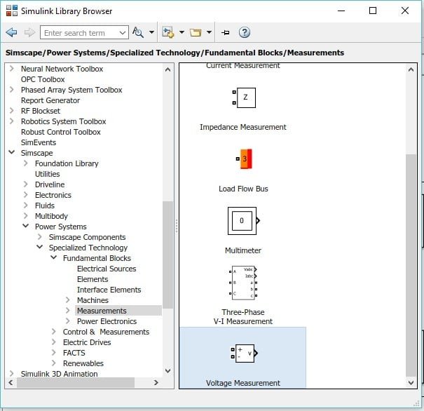
Voltage Measurement
We need a different pulse generator for each of the thyristors; hence, place six different pulse generators for every thyristor. Now for the output side, select the measurement block in the fundamental blocks section, and in this section, select the block named voltage measurement, as shown in the figure below. As we are working with a 3-phase inverter, we need to place three such measuring devices.
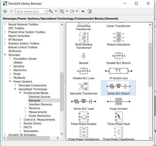
Also, we have to place the load to observe the output of the inverter using the fundamental blocks section. So, now select the block with the name elements, and in this section, select the series RLC branch and place it in the model. Refer to the figure below.
Also, in order to observe the output, we need to place an oscilloscope and three scope blocks from the library browser on the model, as we can see in the figure below.

The last thing is to place the ground from the same section as load, select the block named ground, and place it in the model as shown in the figure below.

Load and Source
At the input side of the bridge we created previously, connect the DC voltage source, and at the output, connect the load (change the RLC load to only a resistive load) with each branch to each row as shown in the figure below.
Arrange all six pulse generators with each of the thyristors and connect them. The phase shift of the first pulse generator will be 0 degrees, whereas the second pulse generator will be 60 degrees, and so on. The parameter settings of the first block are shown in the figure below.

As the phase delay is in seconds, the phase delay of the second pulse generator will be (2e-3)*(1/6), and so on. All six pulse generators connected are shown in the figure below.
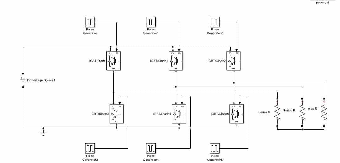
Simulink Model
At the output, connect the voltage measurement across each resistor and connect the scope at the output of each voltmeter, as shown in the figure below.

Simulation
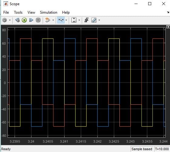
At last, we run the Simulink model as we have been doing in previous tutorials and double-click on the scope to see the output. The output will be a three-phase AC, as shown in the figure below.
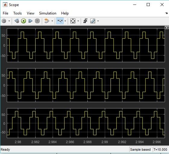
Change the layout of the scope to three frames, and the output will look as shown in the figure below.
Exercise:
- Perform the analysis on single phase inverter using MATLAB’s Simulink.
(Hint: Number of transistor to be used will be 4)
Conclusion
In conclusion, this tutorial provides an in-depth overview of designing and simulating three phase inverter using Simulink. It covers step-by-step procedures along with exaplanations of an example to help us better understand the concept. You can utilize this tutorial to design other three phase inverters. At the end, we have provided an exercise to reinforce the concept of phase inverters. Hopefully, this was helpful in expanding your knowledge of Simulink.
You may also like to read:
- Accident Alarm System Using Pic Microcontroller
- Digital Circuits Simulation using PSpice: Tutorial 10
- UART Communication with Pic Microcontroller( Programming in MPLAB XC8 )
- Arduino Comparator Tutorial with Example
- Microcontroller Booting Process – Reset Sequence
- IOT Based Toll Booth Manager System using pic microcontroller
This concludes today’s article. If you face any issues or difficulties, let us know in the comment section below.
Tried this exact circuit, do not know what I am doing wrong but I do not get the same three phase waveforms at all. I have used the correct switching pulses and checked the waveforms but the output voltages are not right at all.
I think you have to correct the gate pulse sequence…..According to the given circuit diagram the sequence should be IGBT, IGBT5, IGBT1, IGBT3, IGBT2, IGBT4 (0,60,120,180,240,300). I have followed this sequence and got expected result. However, the simulation presentation of this website is awesome. I appreciate the work.
Great Simulation!
from this design how should i get sinusoidal waveform as a output
You are absolutely right about the sequence of the IGBT programming. By using your sequence to program pulse generator , the output waveform is 100% correct.
I mean this sequence. Program the pulse generators which are connected with the IGBT as shown below:
IGBT, IGBT5, IGBT1, IGBT3, IGBT2, IGBT4 (0,60,120,180,240,300)
what is the phase delay of 3rd pulse generator in period ?
what is the phase delay of 3rd pulse generator in period ?
This is a non-working model, the phase delay coefficients of the upper row should be 0-2-4 and the lower row 3-5-1
This model works, the information is lacking in explanation but for the pulse generators I set the frequency to 20ms (50Hz) and on the basis that 1 degree equals 55.6 us then the phase delay values are
0, 3.3e-3, 6.7e-3, 10e-3, 13.3e-3, 16.7e-3.
I numbered the IGBT’s as 1, 3, 5 on the top and 4, 6, 2 on the bottom which aligns the phase sequence to 1, 2, 3, 4, 5 & 6.