In this short guide, we will discuss Arduino’s analog comparator. This will include a brief introduction to the analog comparator including its registers. Then, we will demonstrate these concepts with the help of an Arduino sketch that toggles an LED.

Recommended Components
The following components are used in this project or are helpful for building it with the Arduino.
| Component | How it’s used in this project | Buy on Amazon |
|---|---|---|
| Arduino Uno R3 | The main controller board whose analog comparator is configured and demonstrated in this tutorial. | Check Price |
| Breadboard | Solderless board to build the comparator demo circuit. | Check Price |
| Jumper Wires | Used to wire the potentiometer, LED, and resistor to the Arduino comparator pins. | Check Price |
| 5mm LED | The output LED that indicates the comparator result in the example. | Check Price |
| Resistor Kit (220/4.7k) | Provides the current-limiting resistor in series with the LED. | Check Price |
| 10k Potentiometer | Sets the adjustable reference/input voltage fed to the comparator. | Check Price |
As an Amazon Associate we earn from qualifying purchases. Prices and availability are accurate as of the date/time indicated and are subject to change.
Arduino Comparator Introduction
The ATmega328P chip is used to operate the Arduino UNO board. This chip features an analog comparator module that is used to compare the input voltages at the positive pin AIN0 and the negative pin AIN0. The output of the comparator, ACO, is set when the voltage reading at the positive pin is higher than the voltage reading at the negative pin. This output can then be used to trigger an interrupt including the Timer/Counter1 input capture function or a separate interrupt (triggered at output rise, fall, toggle).
The block diagram below shows the analog comparator found in ATmega328P:
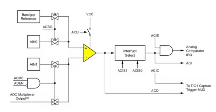
Note: Pins AIN0 and AIN1 are connected externally with Arduino UNO digital pins 6 and 7.
Analog Comparator Registers
The analog comparator is managed by the ACSR register as shown below. All the bits except bit 5 (read only) are readable and writable in case of ACSR which is the analog comparator and status register.
The ACSR register is primarily responsible for controlling the analog comparator.
Bit ACD may be used to turn off the comparator, while bit ACBG can be used to link the bandgap reference to the comparator (A +). The bits ACIE and ACIC control whether the interrupt or input capture is enabled.
| Bit | 7 | 6 | 5 | 4 | 3 | 2 | 1 | 0 | |
| 0x30 (0x50) | ACD | ACBG | ACO | ACI | ACIE | ACIC | ACIS1 | ACIS0 | ACSR |
| Read/Write | R/W | R/W | R | R/W | R/W | R/W | R/W | R/W | |
| Initial Value | 0 | 0 | NA | 0 | 0 | 0 | 0 | 0 |
If the bit ACME in register ADCSRB is set to 1, the comparator is shifted to AIN1 (A-). When ACME is set in ADCSRB and ADEN in ACSRA, the results are the same. Depending on the assignment of the MUX bits, if ACME is set and ADEN is reset, an ADC channel is moved to the comparator.
| Bit | 7 | 6 | 5 | 4 | 3 | 2 | 1 | 0 | |
| (0x7B) | – | ACME | – | – | – | ADTS2 | ADTS1 | ADTS0 | ADCSRB |
| Read/Write | R | R/W | R | R | R | R/W | R/W | R/W | |
| Initial Value | 0 | 0 | 0 | 0 | 0 | 0 | 0 | 0 |
Set the bits ACIS1 and ACIS0 as shown in the table below for comparator interrupt configuration.
| ACIS1 | ACIS0 | Mode |
| 0 | 0 | Comparator Interrupt at level change on ACO |
| 0 | 1 | Reserved |
| 1 | 0 | Comparator Interrupt at falling edge on ACO |
| 1 | 1 | Comparator Interrupt at rising edge on ACO |
Arduino Comparator Example Sketch
Open your Arduino IDE and go to File > New to open a new file. Copy the code given below in that file.
This sketch shows how the analog comparator triggers an interrupt according to the output ACO which in return toggles the onboard LED of Arduino.
// Definition of interrupt names
#include <avr/io.h>
// ISR interrupt service routine
#include <avr/interrupt.h>
const int pLED = 13; // LED at Pin13
const int pAIN1 = 7; // AIN1 at Pin7
volatile boolean iflag = true;
int idx;
// Install the interrupt routine for ACOMP
ISR(ANALOG_COMP_vect)
{
if ( ACSR & (1<<ACO) ) // ACO is set?
{
iflag = false;
digitalWrite(pLED, HIGH);
}
else
{
iflag = true;
digitalWrite(pLED, LOW);
}
}
void setup()
{
Serial.begin(9600);
pinMode(pLED, OUTPUT);
digitalWrite(pLED, LOW);
pinMode(pAIN1, INPUT);
cli();
ADCSRA &= ~(1<<ADEN); // ADC disabled
ADCSRB |= ~(1<<ACME); // AMUX enabled
ACSR = (1<<ACBG) | (1<<ACIE); // ACOMP Interrupt enabled
DIDR1 = (1<<AIN1D) | (1<< AIN0D);
sei();
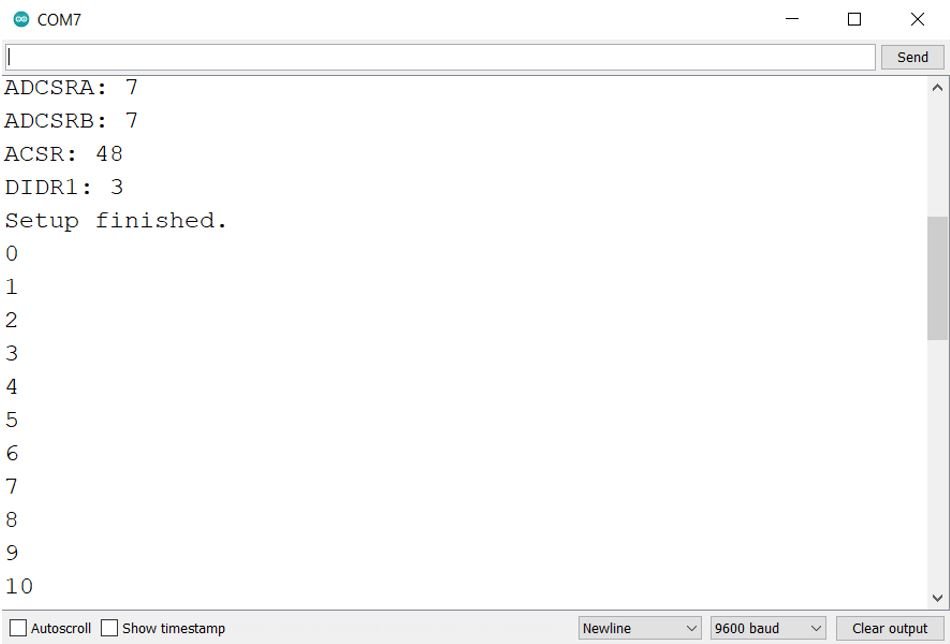
Serial.print("ADCSRA: "); Serial.println(ADCSRA, HEX);
Serial.print("ADCSRB: "); Serial.println(ADCSRB, HEX);
Serial.print("ACSR: "); Serial.println(ACSR, HEX);
Serial.print("DIDR1: "); Serial.println(DIDR1, HEX);
Serial.println("Setup finished.");
}
void loop()
{
if (iflag)
Serial.println(idx); // iflag controls serial output
idx++;
delay(500);
}How the Code Works?
Firstly, include the definition of the interrupt names and the ISR interrupt service routine.
#include <avr/io.h>
#include <avr/interrupt.h>
Create two variables. ‘pLED’ to hold the Arduino pin connected with the onboard LED and ‘idx’ will be incremented inside the main program.
const int pLED = 13;
int idx;
‘pAIN1’ variable holds the Arduino digital pin 7 connected with AIN1.
const int pAIN1 = 7;Create a volatile boolean variable called ‘iflag’ that will be set while toggling the LED. Initially, it is set to ‘true.’
volatile boolean iflag = true;This is the interrupt service routine for the analog comparator.
ISR(ANALOG_COMP_vect)
{
if ( ACSR & (1<<ACO) ) // ACO is set?
{
iflag = false;
digitalWrite(pLED, HIGH);
}
else
{
iflag = true;
digitalWrite(pLED, LOW);
}
}
Inside the setup() function, open the serial communication at the set baud rate. Configure the led pin as an output pin and set its value to LOW. Moreover, we will configure the AIN1 pin as an input pin. Then, we disable the ADC and enable the AMUX. The analog comparator interrupt is enabled. The ADCSRA, ADCSRB, ACSR, DIDR1 values are printed in the serial monitor.
void setup()
{
Serial.begin(9600);
pinMode(pLED, OUTPUT);
digitalWrite(pLED, LOW);
pinMode(pAIN1, INPUT);
cli();
ADCSRA &= ~(1<<ADEN); // ADC disabled
ADCSRB |= ~(1<<ACME); // AMUX enabled
ACSR = (1<<ACBG) | (1<<ACIE); // ACOMP Interrupt enabled
DIDR1 = (1<<AIN1D) | (1<< AIN0D);
sei();
Serial.print("ADCSRA: "); Serial.println(ADCSRA, HEX);
Serial.print("ADCSRB: "); Serial.println(ADCSRB, HEX);
Serial.print("ACSR: "); Serial.println(ACSR, HEX);
Serial.print("DIDR1: "); Serial.println(DIDR1, HEX);
Serial.println("Setup finished.");
}
Inside the loop() function, we increment the variable ‘idx.’
void loop()
{
if (iflag)
Serial.println(idx); // iflag controls serial output
idx++;
delay(500);
}
Demonstration
To see the demonstration of the above code, upload the code to Arduino. But, before uploading code, make sure to select the Arduino board from Tools > Board and also select the correct COM port to which the Arduino board is connected from Tools > Port.

Once the code is uploaded to Arduino, open your serial monitor and set its baud rate.
You may also like to read:
- Arduino RGB LED Control using Android App with MIT App Inventor
- I2C Communication Between Two Arduino Boards
- Arduino Send Sensor Readings to Android app with MIT App Inventor
- RC522 RFID Reader Module with Arduino
- MAX30102 Pulse Oximeter and Heart Rate Sensor with Arduino
- MAX30100 Pulse Oximeter and Heart Rate Sensor with Arduino