ESP12E WiFi Module is the most common WiFi module in most of the products in nowadays. The modules are smaller in size and have internal programming ability with onboard pins. It has an internal 32-bit microcontroller that can perform multiple communications and output signals. The module is programmable with multiple languages and in most modern IoT devices ESP12E is available for creating and network hub and device. ESP12E has all popular network protocols and security encryption in a single chip with fast speed and low power consumption. The module ESP12E is popular due to its cheapness and it has less ping as compare to any other module.
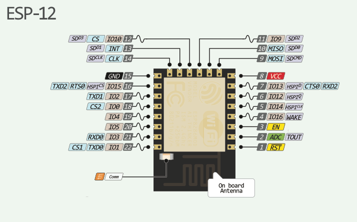
ESP-12E Pinout Diagram
The ESP12E WiFi Module is the best module for WiFi communication. It is because of its onboard microcontroller which generates multiple pins. The pins of ESP12E is a stand-alone device. It is just like a microcontroller with WiFi in a small size. There is a total of 22 pins which offer multiple kinds of communication and all of them are:
Pin Configuration Description
In this section, we will describe details of pinout. We list functionality of each pin one by one.
GPIO Pins
There is a total of 11 I/O pins. Therefore, these pins can perform multiple kinds of input and output functions that are interfaceable with all the TTL/CMOS devices. All GPIO pins are:
- Pin4 – GPIO16
- Pin5 – GPIO14
- Pin6 – GPIO12
- Pin7 – GPIO13
- Pin11 – GPIO9
- Pin12 – GPIO10
- Pin16 – GPIO15
- Pin18 – GPIO0
- Pin19 – GPIO4
- Pin20 – GPIO5
UART Communication Pins
The devices ESP 12E is programmable with UART communication in many IDE. Those UART pins are usable after even programming. Both pins are:
- Pin 21 – RXD0
- Pin 22 – TXD0
- Pin15 – RTS
- Pin13 – CTS
- Pin2 – TXD
ESP12E SPI Communication Pins
The module offers direct SPI communication with itself. This communication uses four pins for proper communication, which are:
- Pin12 – CS0
- Pin10 – MISO
- Pin9 – MOSI
- Pin14 – SCLK
I2C
In ESP12E some GPIO pins are useable for I2C communication. In this communication, only two pins help to communicate. One for clock and other for data. Therefore, in ESP, both are:
- Pin14 – SCL
- Pin2 – SDA
I2S
It isn’t common in every device. The I2S helps to collect, process and transmit the audio signal. The I2S uses 6 pins and in ESP 12E all I2S pins are:
- Pin12 – I2SI_DATA
- Pin13 – I2SI_BCK
- Pin14 – I2SI_WS
- Pin15 – I2SO_BCK
- Pin3 – I2SO_DATA
- Pin2 – I2SO_WS
PWM
In every controller, the ESP 12E can convert it every pin into PWM pins through programming. There are three specifics for the PWM signal. All these pins are:
- Pin12
- Pin13
- Pin15
IR Interface
The IR interface uses modulation and demodulation which requires NEC coding. The ESP12E is interfaceable using the IR interface pins and it is specific to these pins:
- Pin5 – IR_R
- Pin14 – IR_T
ADC
The device has a 10-bit ADC pin, which uses 0-1V range to convert the analog data to digital data.
- Pin2
Power and Control Pins
Power : ESP12E uses the VCC pin to power up the whole module and the ground pin to make the common ground with power supply and other devices
- Pin8 – VCC
- Pin15 – GND
Enable: The devices have an internal digital switch. The enable pin will receive the digital HIGH signal to activate the chip.
- Pin3
Reset: To reset the device the digital will help to reset it through the LOW state. The reset pin is the first pin of the module is:
- Pin1
ESP12E WiFi Module Featues
| FEATURES | DETAIL |
|---|---|
| WiFi Protocols | 802.11 b/g/n |
| Frequency | 2.4-2.5GHz |
| Security Protocol | WPA/WPA |
| Encryption types | WEP/TKIP/AES |
| Network Protocols | IPv4, TCP/UDP/FTP/HTTP |
| Wireless Network | STA / AP / STA + AP |
| Power Input | 3.0 – 3.3V |
| Operating Temperature Capacity | -40 – 125 |
| GPIO | 11 Channels |
| SPI | 1 Channel |
| I2C | 1 Channel |
| I2S | 1 Channel |
| IR Interface | 1 Channel |
| UART | 1 Channel |
| PWM | 3-pins |
| Serial Debug | Available |
| Ethernet | Not Available |
| WiFi | Available |
| Master Mode | Available |
| Slave Mode | Available |
| Hybrid Mode | Available |
| Bluetooth | Not Available |
| Onboard Antenna | Available |
Block Diagram
The block diagram of ESP12E has multiple registers and features which is viewable by a block diagram:

ESP12E Applications
- The device is mostly available in IoT devices.
- The Laptops and Computers also come with ESP 12E.
- The wireless control system also has ESP 12E.
- In smart toys and applications, the module has the best use to control them wirelessly.
How to use ESP12E WiFi Module
To control the device there are two methods, Arduino and FTDI. The Arduino uses UART communication to communicate with ESP12E.

ESP12E is a family of ESP8266. So, Arduino IDE uses “Generic ESP8266” for ESP12E. To upload the device Arduino requires the UART communication pins RX and TX only. During the use of ESP12E, there won’t be any library. The module can operate with the same language Arduino board uses; the PINs will help to communicate through Arduino programming. For Example, to use the built-in LED the following code will help to blink the led.
void setup() {
pinMode(LED_BUILTIN, OUTPUT);
}
void loop() {
digitalWrite(LED_BUILTIN, LOW);
delay(1000);
digitalWrite(LED_BUILTIN, HIGH);
delay1000);
}
In Arduino IDE, if the built-in LED is unknown the LED_BUILTIN will help to initialize the LED pin. There are other protocols in the ESP 12E but to control them Arduino uses external libraries. ESP 12E will require the external libraries to control the other protocols like SPI, WIFI, I2C, HTTP, etc. The module is useable as a master and slave. To use the master/slave the different programming will require. These are the most common libraries in ESP8266.
#include <ESP8266WiFi.h>
#include <ESP8266mDNS.h>
#include <WiFiClient.h>
#include "ESP8266WiFi.h"
#include <ESP8266WiFiMesh.h>
#include <ESP8266WiFiMulti.h>
#include <LittleFS.h>
ESP12E WiFi Module Command Mode
The module also comes with command mode. It comes with command mode by default. The command mode uses the baud rate of 115200. The Arduino COM monitor is useable for command mode. The following commands will help to send the data to the module to affect the default setting.
- AT – To check the module connectivity.
AT+RST – To reset the ESP12E through command - AT+GMR – Generate the list of firmware installed.
- AT+CWLAP – To list out all available networks in the range of the ESP
- AT+CWJAP=” SSID”,” PASSWORD” – Add manual data of a WiFi network to connect the module with it.
- AT+CWJAP=””,”” Disconnect the module from any WiFi connection
- AT+CIFSR – Generate the connect IP and the Mac Address.
- AT+CWMODE= – To set the WiFi modes of the ESP12E
- AT+CWMODE? – It will decide the ESP function, how it is going to act. If WiFi needs to act as a WiFi station then 1 will require. To make it a WiFi access point the 2 will do that. The module can act as a hybrid, to makes it hybrid use the 3 with the command and WiFi will help to make it.
ESP12E Arduino Interfacing Example
In this example, we will use the module as a WiFi access point. The module will have its WiFi name and WiFi password. All the WiFi stations will able to connect with it with the use of passwords directly.

The following code will help to make the ESP12E as a WiFi access point.
#include <ESP8266WiFi.h>
void setup()
{
Serial.begin(115200);
WiFi.softAP("SSID-NAME-HERE", "WIFI-PASS(8 MAX)");
void loop()
{
Serial.printf("Stations connected = %d\n", WiFi.softAPgetStationNum());
delay(3000);
}
The library will require to make the WiFi mode an access point. The WiFi.softAP will helpful in describing the WiFi name and password. Once it’s done, the loop will have a WiFi.softAPgetStationNum() to get the detail of the number of connected devices. Once the device is connected there will be an increment in the value unless it gets disconnected. The module can act as a hybrid by using another method which is by AT command:
AT+CWMODE=2
The command will help to make the module an access point without programming. The other thing like device name and password will be able to change/make using the following commands:
AT+CWJAP=" SSID"," PASSWORD"
The SSID should be replaced with WiFi name and Password with WiFi password and it should be a maximum 8 in numbers.
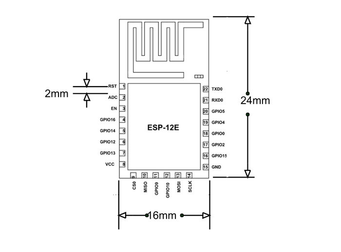
2D Physical Diagram
Other Wireless Modules:
The device drawing shows a total of 12 GPIO pins, but the text states there are 11 and identifies the functions of 11 pins. The drawing shows GPIO2, but the text does not mention it or describe its function. Why is GPIO2 omitted from the text?
The image also shows 12 Pwm channels but then says it only has 3 Pwm what gives?
first picture is wrong. look in your text for SPI connection and compare to picture
Hi, the Pinout diagram is right. But there was an issue with the text. But we fixed it now.
Pin12 – I2SI_DATA
Pin13 – I2SI_BCK
Pin14 – I2SI_WS
Pin15 – I2SO_BCK
Pin3 – I2SO_DATA
Pin2 – I2SO_WS
Pin 15 according to the pin diagram is Ground.
#include
void setup()
{
Serial.begin(115200);
WiFi.softAP(“SSID-NAME-HERE”, “WIFI-PASS(8 MAX)”);
void loop()
{
Serial.printf(“Stations connected = %d\n”, WiFi.softAPgetStationNum());
delay(3000);
}
The above code does not compile.
Please correct.