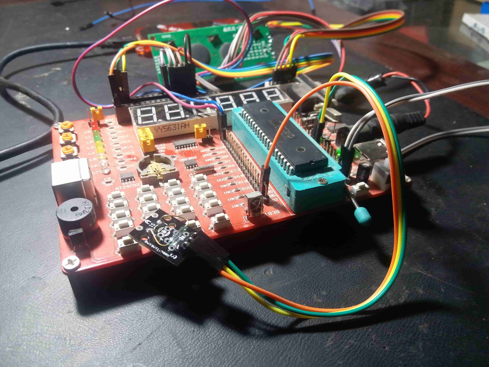
magnetic field detection with pic microcontroller and reed switch, In this tutorial, you will learn to make magnetic field detection circuit using pic microcontroller and reed switch. I will using pic16F877A microcontroller in this tutorial. Magnetic field detection circuits has many applications in embedded systems projects. There are many sensors available in market which are used to detect magnet field. But all those sensor are expensive. In this tutorial we are using a reed switch for magnetic filed detection. Reed Switch is available in very low price. you can purchase it in less than one dollar. I have already posted a article on reed switch interfacing with Arduino Uno R3. So lets start with the introduction to reed switch and how it can used in magnetic field detection circuit. I will also post a article on magnetic field strength measurement soon. 
Introduction to reed switch
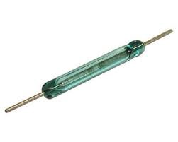
Reed switch is basically electronics device which consists of read contacts. It was first time used by a scientist Bell. Reed switch consists of two electrical contacts which are normally open. These electronics electrodes are made of copper or other electrically conductive materials. Normally these contacts are open. When we bring a magnet close to reed switch, these contact becomes close. So normally it will act like a open circuit and when it is place inside a magnetic filed it will act like close circuit by making contacts short with each other. The picture of reed switch is shown below. 
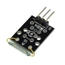
we can not use reed switch alone. Because we need to detect this open and close circuit state of reed switch. So we have use a reed switch module.
In this module reed switch is connected in series with a resistor. one side of reed switch is connected with resistor and other side is connected with the 5 volt power supply. Other side of resistor is connected with ground as shown in picture below.
Reed switch module has three pins as explained below:
- Ground pin
- 5 volt power supply pin
- output signal pin
Output signal pin gives output of 5 volt whenever reed switch detects magnetic field and otherwise output will be zero. So now lets see how we can use this reed switch to detect magnetic field.
How to use reed switch for magnetic field detection
As I mentioned earlier whenever reed switch becomes close to magnetic field. Its contact becomes close and it acts like a close circuit. So we need measure voltage state at the output pin of module. We only need to use input pin of pic microcontroller to read logic high and logic low state of module. If pic microcontroller detects logic high state, its means magnetic field is detected and if microcontroller measures logic low state, it means no magnetic field is detected or no magnetic field is available.
Magnetic field detection sensor interfacing with pic microcontroller
Circuit diagram for reed switch interfacing with pic microcontroller is shown below. Output of reed switch is connected with pin number 6 of PORTB which is configured as digital input pin in code. Buzzer is connect with pin number 1 of PORTE. Buzzer will start giving a sound, whenever reed sensor detects the magnetic field. 
Code for magnetic field detection using pic microcontroller
Code for the magnetic field detection using pic16F877A microcontroller is written using Mikro C for pic compiler.
void main(void)
{


TRISB.B6=1; // use to detect output of reed switch
PORTB.B6=0;
PORTE.B0=0;
TRISE.B0=0; // used as output for relay
while(1) { // Endless loop


if( PORTB.B1==1)
{
PORTE.B0=1; // turn on the relay and magentic filed detected
}
else
{
PORTE.B0=0; // turn off the realy and magnetic field is not detected
}
}
}
So this is all about how to measure magnetic field and how to design magnetic field detection circuit using pic microcontroller and a reed switch.
