Cuk converter circuit design using pic microcontroller, In this article I am going to write about cuk conveter circuit design and its implementation using pic microcontroller. Cuk converter works similar to buck boost converter but in cuk converter output voltage polarity is opposite to that of input voltage polarity. I have already posted articles on buck converter, boost converter and buck boost converter design using PIC16F877A microcontroller. Check following links to read about these converters.
- Buck converter using PIC16F877A microcontroller
- Boost converter using PIC microcontroller
- Buck Boost converter using pic microcontroller
- Push pull converter using Sg3525
What is cuk converter ?
Cuk converter is used to get output voltage less than or greater than input voltage but output voltage polartity is opposite to that of input voltage. Cuk is the name of its cuk converter inventor. Basic circuit diagram of cuk converter is shown below.
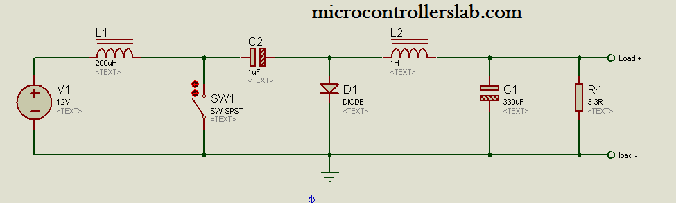
Basic circuit diagram of cuk converter is shown above. But to implement it practically, you need to use a MOSFET, Transistor or IGBT instead of switch. For example if you use Mosfet as switch, you also require a mosfet driver to drive MOSFET in either high side or low side. There are many MOSFET driver IC’s available in market. You can purchase any one of them. I usually use IR2110 MOSFET driver. Because it si easily available in pakistan electronics stores. IR2110 MOSFET driver can be used either as a high side MOSFET driver and low side MOSFET driver. In case of cuk converter, MOSFET is used as a low side switch because load is connected to drain side of MOSFET and source is connected to ground. If you don’t get this point, Don’t worry. You will understand it after reading following article. I have posted a separate article on MOSFET driver IR2110. In which I have disccussed what is MOSFET driver ? What is high side and low side Mosfet driver ? How to use IR2110 as a low side and high side MOSFET driver? For answers of these questions check following articles:
purpose of this article is to give you brief review of how to implement cuk conveter practically. I am not going to discuss theory of cuk converter in this articles. Becuase there are thousands of book available on power electronics. You can easily study cuk converter theory from these books and ways to calculate values of inductors and capacitors used in buck boost converter.
How to select diode and MOSFET as a switch :
To select diode and MOSFET for cuk converter, you should know about current rating of your cuk converter design. For example you want to design cuk converter of rating 42W and constant output voltage of 6 volt. Ouput voltage remains same either input voltage increases or decreases from 6 volt. You want to get regulated output voltage of 6 volt. Now by using power formula you can easily calculate current rating of your cuk converter design. By using values
P = 42 W
V out = 6 v
P = V * I hence I = P / V = 42 / 6 = 7 ampere
Hence current rating of 42W cuk converter design is 7 ampere. Now you should select MOSFET and diode of current rating 7 ampere. You can search on google for diode and MOSFET of 7 Ampere rating.
Practical circuit diagram of cuk converter :
Practical circuit diagram of cuk converter is shown below :
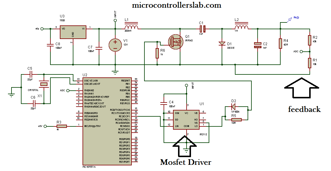
Practical circuit diagram of cuk converter design is shown above. Voltage divider at the output is used as feedback control system. PIC16F877A microcontroller measure output voltage using analog to digital converter. Voltage divider step down the output voltage below 5 volt. Becuase microcontrollers can not read voltage more than 5 volt directly. This measured output voltage is used to increase or decrease duty cycle of pulse width modulation. Duty cycle inrease if output voltage is less than the required output voltage and duty cycle decrease if output voltage is gretaer than the required output voltage. I have posted a separate aticles on how to measure voltage using PIC16F877A microcontroller and how to generate PWM of variable duty cycle. Check following articles to write code for cuk converter control using pic microcontroller.
- How to measure voltage using PIC16F877A microcontroller?
- Pulse width modulation using PIC16F877A microcontroller.
Remember capacitors used in above circuit diagram is polar capacitors and inductors are toriod wound inductors. I hopw after reading this article you will be able to write code and make you reuired cuk converter design. Kindly share this article with others also.
Thank you so much for this useful information. But it would be really helpful if you could also provide with the code for this particular CUK converter application, because in your previous article on PWM, the code provided is using the switches and not automatically run. I would really look for a positive reply from your end.
Hi Bilal,
googling about Cuk-converters I came around your blog with the PIC-based converter.
The feedback from the converter output to the controlling PIC seems unclear for
me. As far as I know, Cuk-converters are inverting converters, i. e. they are
generating a negative output voltage in respect to the input voltage.
You placed a resistor network at the output and fed the divided (negative!) voltage
back to the ADC of the PIC. I don’t know the internals of PIC controllers, but I wonder,
in which way the controller can measure a negative voltage.
Or did I overlook anything?
best regards from Germany
Thomas
you need to use circuit which converts negative voltage into positive voltage with same magnitude. You can use inverting amplifier with unity gain. Invertering op amp converts -ve voltage into +ve. I have not added this circuit in above circuit daigram
You are exactly right about it Thomas and Bilal, it has to have a inverting amplifier or some sort of other circuit to convert the negative voltage to positive because the ground here is common for all circuit since the PWM is being directed to the MOSFET driver and the all circuit which all has a reference to ground.
I would be really interested in some algorithm being discussed here how to control the PWM or error in coding specifically going from 0 to 100% duty cycle how to do it when the error is maximum or what? In case of op-amps and feedback path it can be controlled but in coding. At present i am working on a Current Controlled Digital Synchronous Converter at 10A(max) , 50V…
Arsalan A Rahim
Assistant Professor
EED, University of Engineering & Technology Lahore, Pakistan
Respected sir,
For coding and complete design you can contact me at microcontrollerslabhub@gmail.com
Improved Trans-Z-Source Invert er With
Continuous Input Current and Boost Inversion
Capability USING MICRO CONTROLLER
hi sir
how can i add mosfet driver to isis proteus ?
Hai Sir thanks for information, what should I do to get a frequency of 50khz on this circuit?