Digital multimeter circuit using pic microcontroller. Hi everyone, I was busy with my routine, therefore I was not able to write anything from last three to four months. But from now I will writing technical articles on daily basis. today I am going to share a project with you about Digital multimeter circuit and design using pic microcontroller. Digital multimeter measures AC voltage, AC current, frequency of sine wave and power factor and display it on LCD. I have already posted a complete guide on ac voltage measurement using microcontroller, AC current measurement using microcontroller, Power factor measurement with pic microcontroller and sine wave frequency measurement using microcontroller. I suggest you to read these articles first to get more clear idea about Digital multimeter circuit diagram and code. I have explained all these four electrical quantities measurements in details in those articles.
Digital multimeter circuit components
Digital multimeter circuit consists of following components. Working and brief description these components is given below:
Potential transformer: Voltage transformer steps down the 220V AC voltage to 12V AC voltage. Because microcontroller can not read high voltage directly. We have to provide some kind of circuitry between microcontroller and AC votage source to step down voltage from high voltage to less than 5 volt.

Current transformer: CT is used to step down high current into low current. After current transformer, shunt resistor is used. voltage drop across this shunt resistor is used to measure current. one can also use other type of current sensor like hall effect current sensor to measure current. hall effect sensors are cheaper in price and can measure current up to 30A. I will post an article on ACS712 hall effect current sensor interfacing with pic microcontroller.
Diode rectifier: Diode rectifier is used to convert negative cycle into positive cycle. Because reference voltage for microcontroller is ground. Hence it can not read negative voltage. It is used to convert negative cycle to positive cycle so that negative voltage do not appear across controller.
Zero crossing detection: LM358 is used as comparator to design zero crossing detection circuit. It detects zero crossing of current and voltage wave forms. Because difference in time between two zero crossings is used to measure power factor. you can check power factor controller for more information on this.
Voltage divider : Two resistors are used as a voltage divider to step down voltage further less than 5 volt. Because step down voltage to 12V. It is still high voltage for microcontroller. Voltage divider step down it less than 5 volt. It is safe voltage to measure.
PIC18F4550 microcontroller: It is a main part of Digital multimeter circuit. you can say it is a heart of Digital multimeter. It measures all parameters and make necessary calculations on measured data and displays on LCD.
So this was all about main components of Digital multimeter circuit. To write code for this project one should know how to use analog to digital converter of pic microcontroller. How to measure analog voltage. How to use timers for time measurement. How to interface LCD with pic microcontroller. So I recommend you to read about them first so that you can write code easily for Digital multimeter circuit.
Digital multimeter circuit diagram
Circuit diagram of Digital multimeter is given. I have already explained components of circuit. Two analog to digital converter channels are used. These two channels are used to measure ac voltage and current. Pic microcontroller have built in ADC’s. These ADC convert analog value into digital number. Microcontroller converts it back into voltage and current according to code stored in program memory.
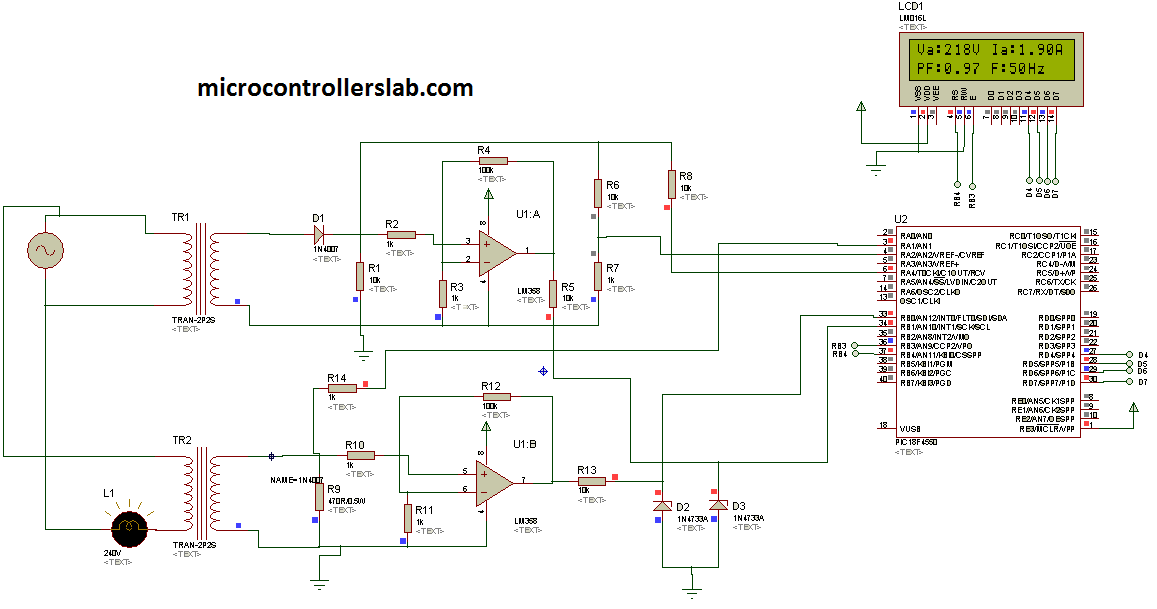
Timer is used to measure frequency of sine wave or ac signal. Two zener diodes are used to protect greater voltages appearing across controllers pins.As shown in above circuit diagram, LCD is showing voltage, current, frequency and power factor. Ac power measurement feature can also be included in this project. Code for this project is written is using Mikro C compiler. If you want to purchase code and simulation of this project contact me at admin@microcontrollerslab.com
Hi How are you if you please i want to purchase code and simulation of this project
Digital multimeter circuit using pic microcontroller
Aslamualikum I also want learn pic programming can u help me