In this ESP32 user guide, we will show you how to encrypt messages while using ESP-NOW protocol while wirelessly transferring data from one ESP32 to another. In previous ESP-NOW getting started tutorials we looked upon this wireless protocol in depth where we performed wireless communication between ESP32 devices. This communication protocol is a low-power, secure, and direct wireless communication protocol that enables multiple ESP32 devices to communicate with each other without the need for WIFI or a router.
In this guide, however, we will take a step ahead and encrypt the messages that we want to transfer between the ESP32 sender and receiver boards. This will secure our data. The basic method implemented for the message encryption will be CCMP which uses a Primary Master Key (PMK) and Local Master Keys (LMK). Let us show you how to achieve this using Arduino IDE!
ESP-NOW Protocol Introduction
Using ESP-NOW, we can perform one way and even two-way communication between ESP MCU devices without using a Wi-Fi network. It allows low overhead peer-to-peer wireless data transfers but in small packets. A maximum of 250 bytes of data can be transferred. Thus if a larger amount of data needs to be transferred then using this protocol is not useful. Using ESP-NOW, the connection protocol is simplified which results in low power consumption as a lesser amount of time is required for the transmission of data. Additionally, the ESP-NOW uses the same 2.4 GHz band as the Wi-Fi but does not need to connect or interfere with the local network connection. It is a fast and convenient communication protocol for the transmission of a smaller amount of data.

ESP32 ESP-NOW Key Features
- One-to-one transmission of data (both encrypted and unencrypted).
- Supports both encrypted and unencrypted peer devices. For encrypted devices, there is a limitation of a maximum of 10 peers in the station mode and a maximum of 6 in the SoftAP or a mixture of both modes. However, for unencrypted devices, a maximum of 19 devices are allowed with no limitation of the mode they are operating in.
- A maximum of 250 bytes of data can be transmitted in the form of small packets.
- It generates a callback function that notifies the application layer whether the data was transmitted successfully or not.
To initialize the ESP-NOW connection, we will have to pair our ESP32 boards first. This connection will stay regardless of any one of the board restarts and the transmission will continue smoothly.
ESP-NOW Message Encryption using CCMP Method
The Counter Mode Cipher Block Chaining Message Authentication Code Protocol (CCMP) mode is a security protocol which is especially created for Wireless LAN devices. The ESP-NOW protocol uses this security method to encrypt messages. The CCMP uses a Primary Master Key (PMK) and Local Master Keys (LMK) to encrypt the messages. The Primary Master Key also known as PMK is commonly used to encrypt the Local Master Key using the AES-128 algorithm. Moreover, the Local Master Key encrypts the vendor specific action frame. Both types of keys have a size of 16 bytes which is set by the user in code. Both the sender and receiver boards should be programmed with the same PMK and LMK keys to successfully transfer data.
ESP-NOW One-way Communication Message Encryption Project Overview
Now, let’s learn how to send encrypted data from one ESP32 board to another, using the ESP-NOW protocol. We will use the simplest configuration, where one ESP32 board acts as the sender and the other ESP32 board acts as the receiver. You can use the method given below to transmit encrypted sensor data or any type of information from one ESP board to another. We will keep it simple and create a structure in our sketch which will hold two random numbers from 0 to 100 (num1 and num2) and a count variable that will denote the number of messages sent. The sender ESP32 will send this structure to the receiver ESP32.
To encrypt our message structure we will follow a number of steps. Firstly, the sender board will set its Primary Master Key using the function esp_now_set_pmk(). Next, the sender uses the receiver ESP32 board’s MAC address to add it as a peer. At that point, the local master key is also configured by the sender. Now the receiver board sets the same PMK as the sender board and adds the sender board as a peer. At this point, the local master key is also configured for the receiver. Note that the LMK will be the same for both boards. The sender then transfers the message to the receiver which receives it via ESP-NOW protocol.
For this project, we will require two Arduino sketches one for the sender and the other for the receiver.
Setting up Arduino IDE
We will use Arduino IDE to program our ESP32 development boards. Thus, you should have the latest version of Arduino IDE. Additionally, you also need to install the ESP32 plugin. If your IDE does not have the plugin installed you can visit the link below:
Installing ESP32 library in Arduino IDE and upload code.
Now, first, we will introduce you to an Arduino sketch to find the MAC Address of both the receiver and the sender ESP32 development board. The sketch will display our ESP32 module’s MAC address on the serial monitor which we will later use in the master and sender sketches.
Arduino Sketch for obtaining the MAC Address for the ESP32 board
Open your Arduino IDE and go to File > New to open a new file. Copy the code given below in that file and save it.
#include "WiFi.h"

void setup(){
  Serial.begin(115200);
  WiFi.mode(WIFI_MODE_STA);
  Serial.println(WiFi.macAddress());
}

void loop(){

}
In the setup() function, we are first setting our ESP32 board in station mode. Then by using the WiFi.macAddress() method we will obtain the unique MAC address in our serial monitor.
Make sure you choose the correct board and COM port before uploading your code to the board. Go to Tools > Board and select ESP32 Dev Module. Next, go to Tools > Port and select the appropriate port through which your board is connected.
Click on the upload button to upload the code into the ESP32 development board. Press its ENABLE button after the sketch has been uploaded.

In your Arduino IDE, open up the serial monitor and you will be able to see the unique MAC address of your ESP32 module.
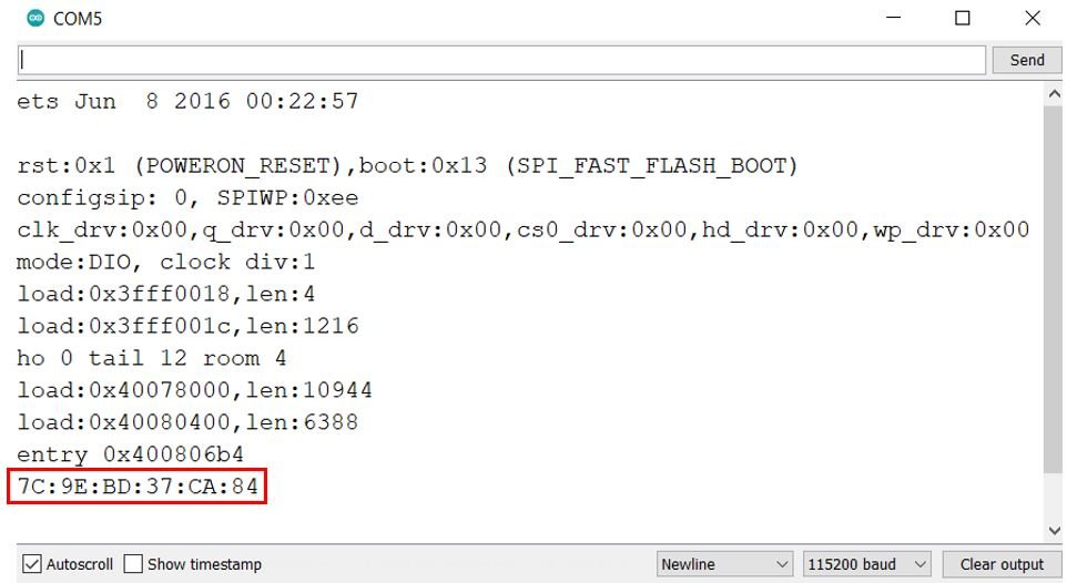
Find the MAC Address of both the sender and receiver ESP32 boards as we will require them in the later sketches.
ESP-NOW Encrypted ESP32 Arduino Sketch for Sender Side
Open your Arduino IDE and go to File > New to open a new file. Copy the code given below in that file and save it. This sketch follows the points given below:
#include <esp_now.h>
#include <WiFi.h>

uint8_t receiverAddress[] = {0x84, 0xCC, 0xA8, 0x5E, 0x52, 0x44};

static const char* PMK_KEY = "123hjk9i0ii67bte";
static const char* LMK_KEY = "0ii67bte123hjk9i";

typedef struct struct_message {
    int count;
    int num1;
    int num2;
} struct_message;

struct_message message;
int count;

void OnDataSent(const uint8_t *mac_addr, esp_now_send_status_t status) {
  Serial.print("\r\nLast Packet Send Status:\t");
  Serial.println(status == ESP_NOW_SEND_SUCCESS ? "Delivery Success" : "Delivery Fail");
}

esp_now_peer_info_t peerInfo;

void setup() {
  Serial.begin(115200);
  WiFi.mode(WIFI_STA);

  if (esp_now_init() != ESP_OK) {
    Serial.println("There was an error initializing ESP-NOW");
    return;
  }

  esp_now_set_pmk((uint8_t *)PMK_KEY);

  memcpy(peerInfo.peer_addr, receiverAddress, 6);
  peerInfo.channel = 0;
  for (uint8_t i = 0; i < 16; i++) {
    peerInfo.lmk[i] = LMK_KEY[i];
  }
  peerInfo.encrypt = true;

  if (esp_now_add_peer(&peerInfo) != ESP_OK){
    Serial.println("Failed to add peer");
    return;
  }

  esp_now_register_send_cb(OnDataSent);
}
void loop() {
  static unsigned long lastEventTime = millis();
  if ((millis() - lastEventTime) > 5000) {
    lastEventTime = millis();
    message.count = count++;
    message.num1 = random(0,100);
    message.num2 = random(0,100);

    esp_err_t result = esp_now_send(receiverAddress, (uint8_t *) &message, sizeof(message));
    if (result == ESP_OK) {
      Serial.println("Sent with success");
    }
    else {
      Serial.println("Error sending the data");
    }
  }
}
How the Code Works?
Lets understand how the code works for the sender ESP32 board.
Including Libraries
Firstly, we will include the necessary libraries. For the sender sketch, we are using two of them. These include esp_now.h for the ESP-NOW communication protocol and WiFi.h will allow our ESP32 board to use the Wi-Fi functionalities.
#include <esp_now.h>
#include <WiFi.h>
Specifying Receiver MAC Address
Secondly, we will specify the MAC Address of the ESP32 board which will act as the receiver. Use the sketch above to find the MAC address. Replace the address with the unique MAC address of your own ESP32 board. You can use the sketch which was given previously, to find the MAC address of your module.
uint8_t masterMacAddress[] = {0x7C, 0x9E, 0xBD, 0x37, 0xCA, 0x84};Specifying PMK and LMK
Next, we will define two global variables called ‘PMK_KEY’ and ‘LMK_KEY’ that will hold the PMK and LMK respectively. You can use any combinations of letters and numbers to create a key but make sure its length is 16 bytes. Use the following Online Byte Counter to calculate the size of your key.
Note: Make sure the sender and receiver board sketches have the same set of PMK and LMK defined.
static const char* PMK_KEY = "123hjk9i0ii67bte";
static const char* LMK_KEY = "0ii67bte123hjk9i";
Defining structure for sending data
Now, we will define a structure named ‘struct_message.’ Inside the structure, we will initialize the variables which will hold our data that we will transmit to the receiver board via ESP-NOW. These include the ‘count’ variable that denotes the number of data packets sent, ‘num1’ and ‘num2’ which are integer varaiables.
typedef struct struct_message {
    int count;
    int num1;
    int num2;
} struct_message;
Next, we will create a new variable of type struct_message and call it message. This will be used later on in the sketch to acquire the data and transmit it accordingly.
struct_message message;
onDataSent()
The onDataSent() function acts as the callback function which we will define now. It will be used as a parameter when we will register this callback function for sending messages. This prints whether the message was successfully delivered or not on the serial monitor whenever a message will be sent from the ESP32 sender side.
void OnDataSent(const uint8_t *mac_addr, esp_now_send_status_t status) {
  Serial.print("\r\nLast Packet Send Status:\t");
  Serial.println(status == ESP_NOW_SEND_SUCCESS ? "Delivery Success" : "Delivery Fail");
}
setup()
Inside the setup() function, we will open a serial connection at a baud rate of 115200 and set up the ESP32 board in station mode.
 Serial.begin(115200);
 WiFi.mode(WIFI_STA);
The following lines of code will initialize the ESP-NOW protocol. In case of an unsuccessful connection, the serial monitor will display ‘Error initializing ESP-NOW.’
  if (esp_now_init() != ESP_OK) {
    Serial.println("There was an error initializing ESP-NOW");
    return;
  }
We will set the Primary Master Key of the device by calling esp_now_set_pmk() function.
esp_now_set_pmk((uint8_t *)PMK_KEY);Next, we will register the receiver ESP32 board as a peer, set its LMK and set the encryption property as true.
memcpy(peerInfo.peer_addr, receiverAddress, 6);
  peerInfo.channel = 0;

  for (uint8_t i = 0; i < 16; i++) {
    peerInfo.lmk[i] = LMK_KEY[i];
  }

  peerInfo.encrypt = true;
Now add the receiver ESP32 board as a peer by calling esp_now_add_peer() function. In case of failure of adding the peer, a relevant message will get printed in the serial monitor.
  if (esp_now_add_peer(&peerInfo) != ESP_OK){
    Serial.println("Failed to add peer");
    return;
  }
Finally we will register the OnDataSent() function as the callback function. This will make sure that whenever a message will be sent from the sender side, the onDataSent() function will be called.
esp_now_register_send_cb(OnDataSent);loop()
Inside the loop() function, we will transmit the message to the receiver ESP32 board. After every 5 seconds, the following message will be sent:
The count value indicating the number of messages sent and two random integer between 0-100. You can easily change the structure ‘message’ to send data according to your needs.
    message.count = count++;
    message.num1 = random(0,100);
    message.num2 = random(0,100);
Then we will send the message by calling esp_now_send() and monitor if it was sent successfully or not.
    esp_err_t result = esp_now_send(receiverAddress, (uint8_t *) &message, sizeof(message));
    if (result == ESP_OK) {
      Serial.println("Sent with success");
    }
    else {
      Serial.println("Error sending the data");
    }
ESP-NOW Encrypted ESP32 Arduino Sketch for Receiver Side
Open your Arduino IDE and go to File > New to open a new file. Copy the code given below in that file and save it. This sketch follows the points given below:
#include <esp_now.h>
#include <WiFi.h>

uint8_t masterMacAddress[] = {0x84, 0xCC, 0xA8, 0x5E, 0x53, 0x44};

static const char* PMK_KEY = "123hjk9i0ii67bte";
static const char* LMK_KEY = "0ii67bte123hjk9i";

typedef struct struct_message {
    int count;
    int num1;
    int num2;
} struct_message;

struct_message message;

void printMAC(const uint8_t * mac_addr){
  char macStr[18];
  snprintf(macStr, sizeof(macStr), "%02x:%02x:%02x:%02x:%02x:%02x",
           mac_addr[0], mac_addr[1], mac_addr[2], mac_addr[3], mac_addr[4], mac_addr[5]);
  Serial.println(macStr);
}

void OnDataRecv(const uint8_t * mac_addr, const uint8_t *incomingData, int len) {

  Serial.print("Packet received from: ");
  printMAC(mac_addr);

  memcpy(&message, incomingData, sizeof(message));
  Serial.print("Bytes received: ");
  Serial.println(len);
  Serial.print("Packet number: ");
  Serial.println(message.count);
  Serial.print("Number 1: ");
  Serial.println(message.num1);
  Serial.print("Number 2: ");
  Serial.println(message.num2);
  Serial.println();
}

esp_now_peer_info_t peerInfo;

void setup() {
  Serial.begin(115200);
  WiFi.mode(WIFI_STA);

  if (esp_now_init() != ESP_OK) {
    Serial.println("There was an error initializing ESP-NOW");
    return;
  }

  esp_now_set_pmk((uint8_t *)PMK_KEY);

  memcpy(peerInfo.peer_addr, masterMacAddress, 6);
  peerInfo.channel = 0;

  for (uint8_t i = 0; i < 16; i++) {
    peerInfo.lmk[i] = LMK_KEY[i];
  }

  peerInfo.encrypt = true;

  if (esp_now_add_peer(&peerInfo) != ESP_OK){
    Serial.println("Failed to add peer");
    return;
  }

  esp_now_register_recv_cb(OnDataRecv);
}
void loop() {

}
How the Code Works?
Lets understand how the code works for the receiver ESP32 board.
Including Libraries
Firstly, we will include the necessary libraries. For the receiver sketch, we are also using the same two libraries which we did for the sender sketch. These include esp_now.h for the ESP-NOW communication protocol and WiFi.h will allow our ESP32 board to use the Wi-Fi functionalities.
#include <esp_now.h>
#include <WiFi.h>
Specifying Sender MAC Address
Secondly, we will specify the MAC Address of the sender ESP32 board which acts as the master. Use the sketch above to find the MAC address. Replace the address with the unique MAC address of your own ESP32 board. You can use the sketch which was given previously, to find the MAC address of your module.
uint8_t masterMacAddress[] = {0x84, 0xCC, 0xA8, 0x5E, 0x53, 0x44};Specifying PMK and LMK
Next, we will define two global variables called ‘PMK_KEY’ and ‘LMK_KEY’ that will hold the PMK and LMK respectively.
Note: Make sure the sender and receiver board sketches have the same set of PMK and LMK defined.
static const char* PMK_KEY = "123hjk9i0ii67bte";
static const char* LMK_KEY = "0ii67bte123hjk9i";
Defining structure for receiving data
Now, we will define the same structure named ‘struct_message’ which we did for the sender sketch. This structure will be used to receive the data that will be received from the receiver ESP32 board via ESP NOW. Make sure that the structure is the same in both the sketches.
typedef struct struct_message {
    int count; // must be unique for each sender board
    int num1;
    int num2;
} struct_message;
Next, we will create a new variable of type struct_message and call it a message. This will be used later on in the sketch to receive the data.
struct_message message;The printMAC() function is responsible for printing the MAC address of the sender ESP32 board in the serial monitor.
void printMAC(const uint8_t * mac_addr){
  char macStr[18];
  snprintf(macStr, sizeof(macStr), "%02x:%02x:%02x:%02x:%02x:%02x",
           mac_addr[0], mac_addr[1], mac_addr[2], mac_addr[3], mac_addr[4], mac_addr[5]);
  Serial.println(macStr);
}
OnDataRecv()
The OnDataRecv() function acts as the callback function which we will define now. It will be used as a parameter when we will register this callback function for receiving messages. This prints the message on the serial monitor whenever a message is received from the ESP32 sender side along with the MAC address of the sender board.
void OnDataRecv(const uint8_t * mac_addr, const uint8_t *incomingData, int len) {

  Serial.print("Packet received from: ");
  printMAC(mac_addr);

  memcpy(&message, incomingData, sizeof(message));
  Serial.print("Bytes received: ");
  Serial.println(len);
  Serial.print("Packet number: ");
  Serial.println(message.count);
  Serial.print("Number 1: ");
  Serial.println(message.num1);
  Serial.print("Number 2: ");
  Serial.println(message.num2);
  Serial.println();
}
setup()
Inside the setup() function, we will open a serial connection at a baud rate of 115200 and set up the ESP32 board in station mode.
 Serial.begin(115200);
 WiFi.mode(WIFI_STA);
The following lines of code will initialize the ESP-NOW protocol. In case of an unsuccessful connection, the serial monitor will display ‘Error initializing ESP-NOW.’
  if (esp_now_init() != ESP_OK) {
    Serial.println("There was an error initializing ESP-NOW");
    return;
  }
We will set the Primary Master Key of the device by calling esp_now_set_pmk() function.
esp_now_set_pmk((uint8_t *)PMK_KEY);Next, we will register the sender ESP32 board as a peer, set its LMK and set the encryption property as true.
memcpy(peerInfo.peer_addr, masterMacAddress, 6);
  peerInfo.channel = 0;

  for (uint8_t i = 0; i < 16; i++) {
    peerInfo.lmk[i] = LMK_KEY[i];
  }

  peerInfo.encrypt = true;
Now add the sender ESP32 board as a peer by calling esp_now_add_peer() function. In case of failure of adding the peer, a relevant message will get printed in the serial monitor.
if (esp_now_add_peer(&peerInfo) != ESP_OK){
    Serial.println("Failed to add peer");
    return;
  }
Finally we will register the OnDataRecv() function as the callback function. This will make sure that whenever a message will be received from the sender side, the OnDataRecv() function will be called.
esp_now_register_recv_cb(OnDataRecv);Demonstration ESP32 ESP-NOW One Way Communication Encrypted Messages
Now after saving both of the sender and receiver sketches, upload them onto their respective ESP32 boards.
First, open the sender sketch. Choose the correct board and COM port before uploading your code to the sender ESP32 board. Go to Tools > Board and select ESP32 Dev Module.

Next, go to Tools > Port and select the appropriate port through which your board is connected.

Click on the upload button to upload the code into the ESP32 board (sender). After you have uploaded your code to the board press its ENABLE button.
Next, follow the same steps and upload the receiver side sketch to the receiver ESP32 module. Make sure you choose the correct COM port through which it is connected. Notice, both of the boards will be connected to different COM ports so select the COM port accordingly. Click on the upload button to upload the code into the ESP32 board (receiver). After you have uploaded your code to the board press its ENABLE button.
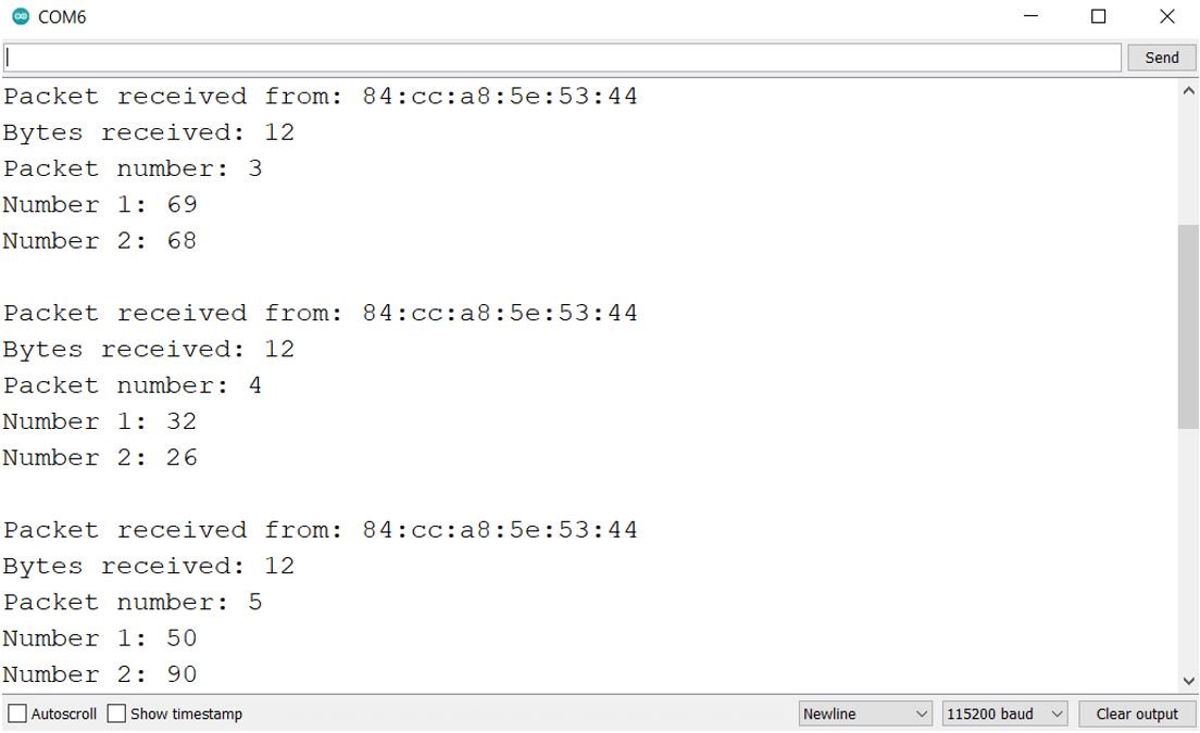
Now, open both serial monitors. You will be able to see the messages being displayed on the receiver side after every 5 seconds.
In the sender side’s serial monitor you will be able to view the text that the message was successfully delivered.
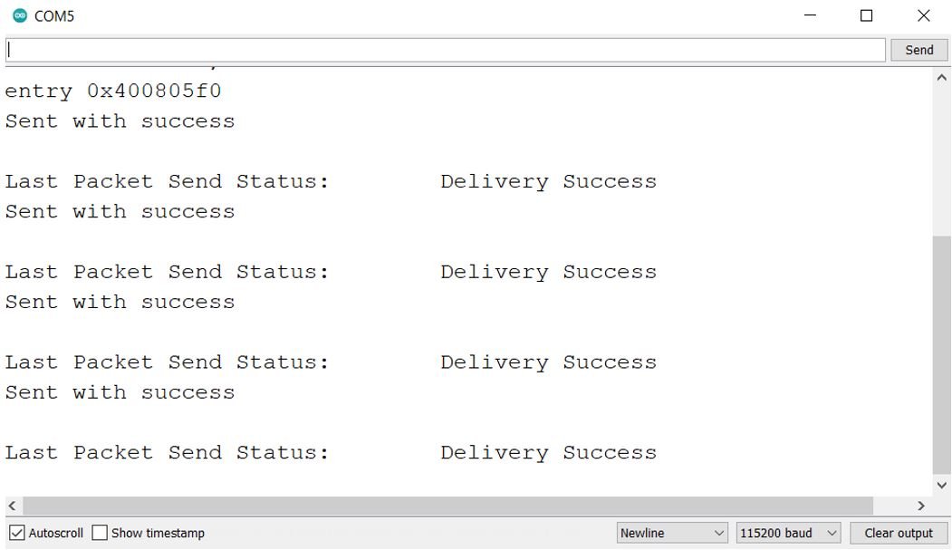
Notice that both COM ports are different. In our case, it is COM5 for the receiver side and COM6 for the sender side.
You may also like to read:
- ESP32 ESP-NOW Getting Started Tutorial with Arduino IDE
- ESP32 ESP-NOW Two way Communication (Arduino IDE)
- ESP32 ESP-NOW Send Data to Multiple boards (One to Many Communication)
- ESP32 ESP-NOW Receive Data from Multiple boards (Many to One Communication)
- ESP32 ESP-NOW and Wi-Fi Web Server using Arduino IDE