In this tutorial, we will learn to use interrupts and timers of ESP8266 NodeMCU using Arduino IDE. By using ESP8266 interrupt, we will be able to detect changes on GPIO pins without the need to continuously poll GPIO pins. Whenever an interrupt occurs, we can execute a certain function that should execute on state change of a specific GPIO pin. In other words, it will make ESP8266 code event-driven instead of just sequential execution of code.
In this tutorial, we will build an example project to design a motion detection system through a PIR motion sensor and ESP8266 interrupts. This PIR motion sensor will be interfaced with one of the GPIO pins of ESP8266 NodeMCU board. We will also connect an indication LED with one GPIO pin. Whenever motion will be detected through a PIR motion sensor, an interrupt will be triggered, a timer will be activated and a LED will turn ON for a set number of seconds. After the timer stops, the LED will turn OFF. In other words, this tutorial is a motion detection project using ESP8266 timers, interrupts, PIR sensor, and Arduino IDE.
We have a similar guide with ESP32 using Arduino IDE as well as in MicroPython:
- ESP32 Interrupts and Timers with PIR Sensor using Arduino IDE
- MicroPython: Interrupts with ESP32 and ESP8266 – PIR Sensor Interfacing Example
By the end of this article you will be able to:
- Known how to use ESP8266 interrupts and timers using Arduino IDE
- Blink an LED using timers
- Interface PIR motion sensor and LED with ESP8266 board
- ESP8266 example sketch with PIR motion sensor and LED
Prerequisites
We will use Arduino IDE to program our ESP8266 development boards. Thus, you should have the latest version of Arduino IDE. Additionally, you also need to install the ESP8266 plugin. If your IDE does not have the plugin installed you can visit the link below:
Installing ESP8266 library in Arduino IDE and upload code
Interrupts Introduction
Interrupts are used to handle events that do not happen during the sequential execution of a program. For example, we want to perform certain tasks and these tasks execute sequentially in your Arduino program. But there are few tasks that only execute when a special event occurs such as an external trigger signal to the digital input pin of a microcontroller.
An external interrupt or a ‘hardware interrupt’ is caused by the external hardware module. For example, there is a Touch Interrupt which happens when touch is detected and a GPIO interrupt when a key is pressed down. In this tutorial, the interrupt will be triggered when the motion will be detected.
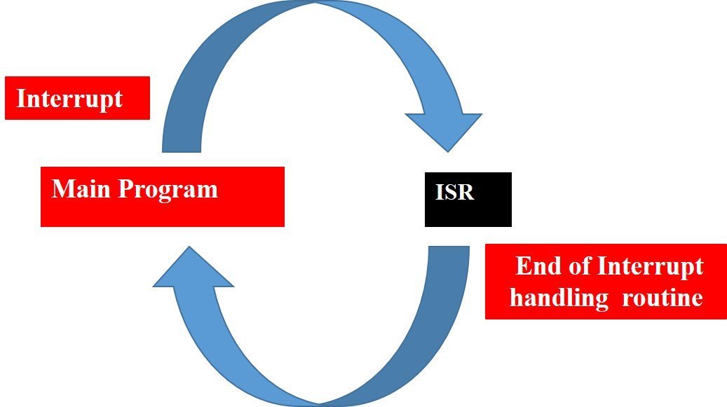
With interrupt, we do not need to continuously check the state of the digital input pin. When an interrupt occurs (a change is detected), the processor stops the execution of the main program and a function is called upon known as ISR or the Interrupt Service Routine. The processor then temporarily works on a different task (ISR) and then gets back to the main program after the handling routine has ended. This is shown in the figure below.
An example can be that of pressing a push button or motion detection with a PIR Sensor. In both cases, a push button or a PIR motion sensor can be used to trigger an interrupt. Therefore, when an external event occurs, the processor stops what it is doing and executes the interrupt service routine which we define for the respective event. After that, it returns to the current program. External Interrupts are extremely useful because with their help we do not have to constantly monitor the digital input pin state.
ESP8266 Interrupts Pins
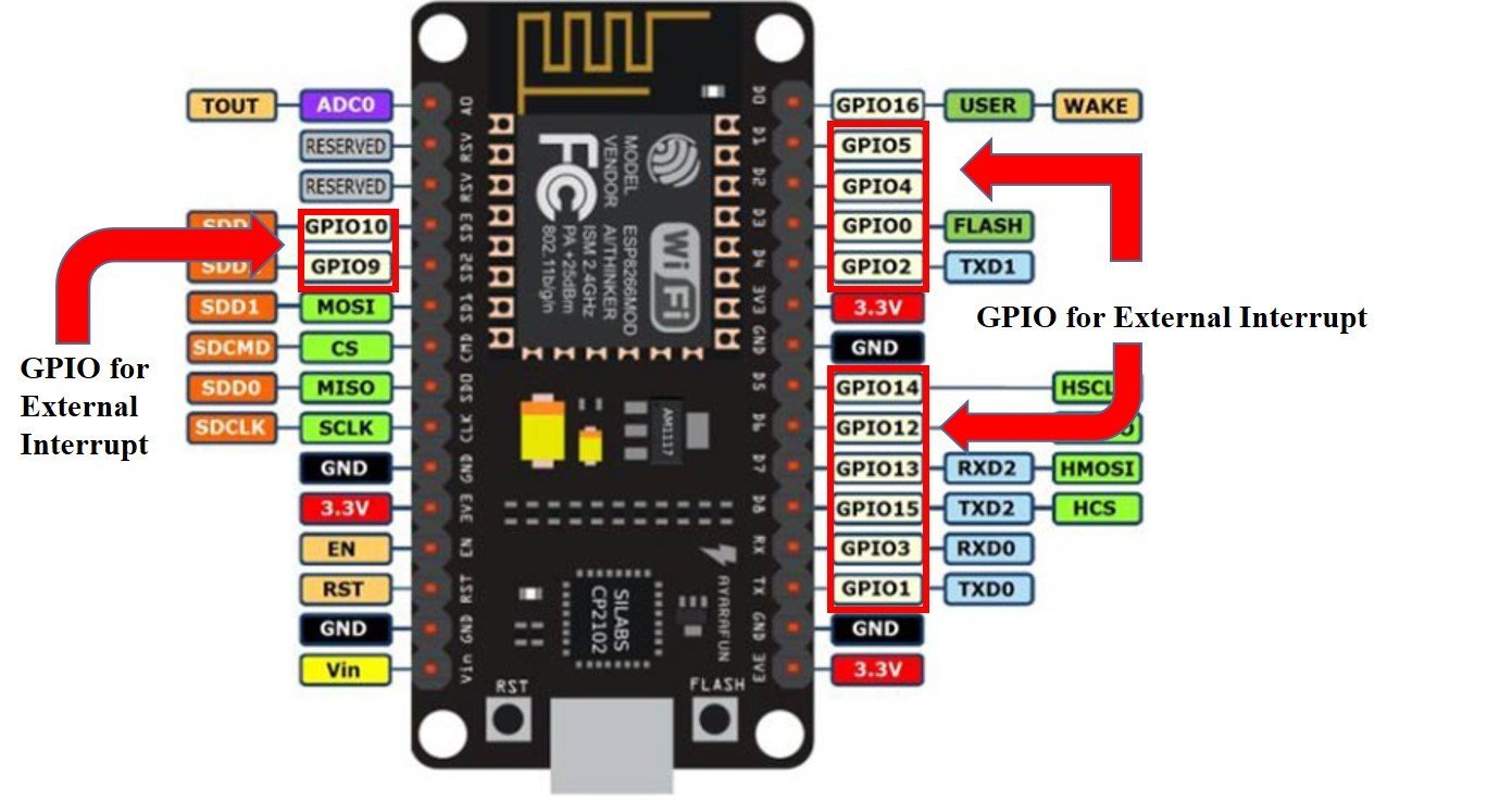
For ESP8266, we can use all the GPIO pins except for GPIO16 to generate external interrupt. The figure below shows the GPIO pins that can be used.
Configuring ESP8266 Interrupts in Arduino IDE
Now let us look at how to set up external interrupts in our ESP8266 development boards using Arduino IDE. The following steps need to be followed.
We will use the following function to configure an interrupt in Arduino IDE:
attachInterrupt(digitalPinToInterrupt(pin), ISR, mode)The attachInterrupt() function takes in three arguments:
- digitalPinToInterrupt(pin): This is a function which takes in the GPIO pin of the ESP8266 board as a parameter inside it. The pin denotes the GPIO associated with the pin which will cause an interrupt to occur. For example if setting GPIO2 as an interrupt pin the function will be specified as digitalPinToInterrupt(2). You can use any of the ESP8266 interrupt pins shown in the diagram above, as a parameter inside this function.
- ISR: This is the second argument used to set up an interrupt. It is a special kind of function known as the Interrupt Service Routine which takes in no parameters and also returns nothing. Whenever the interrupt will occur this function will be called.
- mode: This denotes the triggering action for the interrupt to occur. The following four parameters are used to specify the mode:
LOW: This is used to trigger the interrupt when the pin is in a low state.
CHANGE: This is used to trigger the interrupt when the pin changes its state (HIGH-LOW or LOW-HIGH)
RISING: This is used to trigger the interrupt when the pin goes from LOW to HIGH.

FALLING: This is used to trigger the interrupt when the pin goes from HIGH to LOW.

ESP8266 Timers using Arduino IDE
In our PIR motion sensor project, we want the LED to stay ON for a set number of seconds whenever motion is detected and turn OFF after the time ends. To do that, we will use the millis() function which will act as a timer. Using the delay(ms) function is also an option but this function takes in the time in milliseconds as a parameter inside it which denotes the time for which the program code stops running and gets paused.

Instead, we will use the millis() function that does not block the code and returns the time in milliseconds that has passed since the program was run. It is convenient and a preferred choice to use this function instead of delay(ms). By using the millis() function and applying some logic we can easily achieve the effect of a timer.
Blinking LED using millis()
Before proceeding forward with our project with the PIR motion sensor we will first demonstrate a simple example. In this example, we will blink an LED using the millis() function in Arduino IDE after every 2 seconds.
Required Components:
- One ESP8266 development board
- One 5mm LED
- One 220-ohm resistor
- Connecting wires
- Breadboard
Schematic Diagram
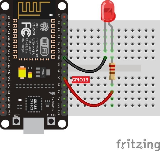
Assemble the circuit as shown below in the schematic diagram.
Connect GPIO13 of ESP8266 with an LED anode terminal. Also, make sure to connect the cathode terminal of the LED with the ground pin of the ESP8266 board through a 220-ohm current limiting resistor. You can use any appropriate output GPIO pin.
Arduino Sketch: Blinking LED using millis()
Open your Arduino IDE and go to File > New. A new file will open. Copy the code given below in that file and save it.
const int led_pin =  13;
int state = LOW;

unsigned long previous_time = 0;
const long interval = 2000;

void setup() {

  pinMode(led_pin, OUTPUT);
}

void loop() {
  unsigned long current_time = millis();

  if (current_time - previous_time >= interval) {

    previous_time = current_time;
    if (state == LOW) {
      state = HIGH;
    } else {
      state = LOW;
    }

    digitalWrite(led_pin, state);
  }
}
How the Code Works?
First, we will define the GPIO pin through which the LED is connected. It is GPIO13 in our case. Also, we will set the state of the LED to LOW so that initially it will be OFF.
const int led_pin =  13;
int state = LOW;
Next, we will create variables to save the interval length in milliseconds and previous_time to monitor the timer. We have set the interval to 2000ms i.e. 2 seconds. After every 2 seconds, the LED will toggle. Feel free to change the interval according to your needs.
unsigned long previous_time = 0;
const long interval = 2000;
Inside the setup function, we will set the GPIO pin as an output pin using pinMode() and passing led_pin and OUTPUT as parameter inside it.
void setup() {

pinMode(led_pin, OUTPUT);
}
Inside the loop() function, we will first define a variable called current_time. This will be set as the millis() function. Thus, the current_time variable will return the time in milliseconds which has passed since the program was run.
unsigned long current_time = millis();Now we will check if the current_time minus the previous_time is greater or equal to 2 seconds then the previous_time will be set as the current_time. Additionally, the LED will also toggle accordingly by updating the variable ‘state’ and using the digitalWrite() function.
if (current_time - previous_time >= interval) {

    previous_time = current_time;
    if (state == LOW) {
      state = HIGH;
    } else {
      state = LOW;
    }

    digitalWrite(led_pin, state);
  }
Thus, after every 2 seconds, the LED will blink without pausing the program code.
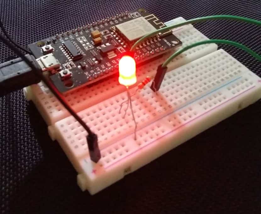
Demonstration
Choose the correct board and COM port before uploading your code to the board. Go to Tools > Board and select NodeMCU 1.0

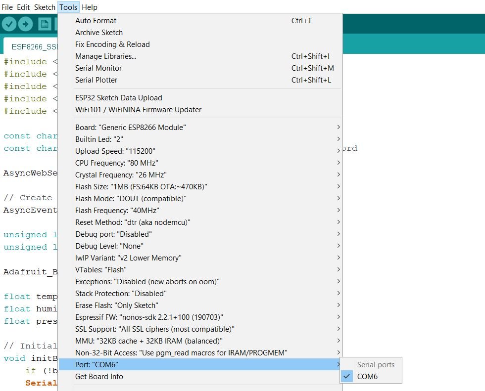
Next, go to Tools > Port and select the appropriate port through which your board is connected.
Click on the upload button to upload the code into the ESP8266 development board.
After you have uploaded your code to the development board, press its RST button.

The LED will start blinking after every 2 seconds.
You may like to read:
PIR Motion Sensor with ESP8266
Now we will proceed further with our project and include an HC-SR501 PIR motion sensor as well.
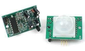
There are many PIR sensors available in the market but we are using passive PIR motion sensors in this project. It can detect a human motion within a range of 10m very easily. It has three pins and the function of each pin is described below:
- GND: It is a ground pin and you should connect it with the ground of your ESP8266 board.
- VDD: It is a power supplier pin and you should connect it with Vin of our ESP8266 board.
- Output: It is an output pin of the PIR sensor. Basically, we get output from this pin. We will connect it with one of the interrupt GPIO pins of our ESP8266 board.
PIR Motion Sensor Working
PIR sensor is a low-cost motion detector sensor. It is a passive motion sensor that means it can only detect something around it and it cannot transmit anything. Whenever there is a motion around the sensor, it will detect the heat of the human body and produces a high output logic 1 at the output of the sensor. Every object emits infrared rays when they are heated and on the same principle, the human body emits IR rays due to body heat. Hence, whenever the motion sensor detects the human body around it, its output becomes high. We can also adjust the sensitivity of this sensor by changing the variable resistors available on the sensor. One variable resistor is for sensitivity adjustment of distance and another variable resistor is for sensitivity adjustment of time that is the amount of time for which the output should be high.
Schematic
After learning all the techniques mentioned previously, now we are ready to proceed with our motion detection project. Now we will learn how to handle interrupts and timers in the ESP8266 board using a PIR sensor and an LED. When a PIR sensor will detect motion, we will turn on the LED for 5 seconds.
The following components are required:
- ESP8266 development board
- One PIR Sensor
- One 5mm LED
- One 220 ohm resistor
- Breadboard
- Connecting Wires
Interfacing PIR Motion Sensor and LED with ESP8266 board
Assemble your circuit as shown in the diagram below:
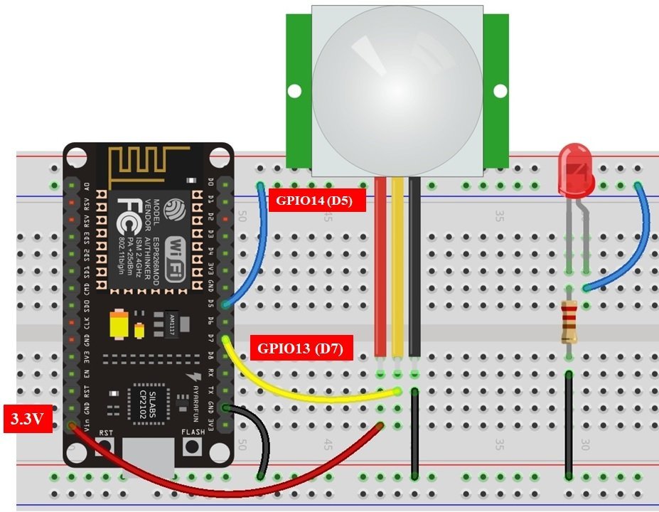
In the above schematic, we can see that GPIO14 is connected with the anode pin of LED, and the cathode pin is connected with the common ground through the 220 ohm resistor.
The PIR Sensor which we are using in this tutorial consists of three pins. Two of them are power supply pins such as VCC and ground pins. We can power PIR motion sensor directly from the ESP8266 3.3V power pin as shown in the above schematic diagram. The centre pin is the output pin which provides an active high pulse whenever motion is detected. Otherwise, this pin remains active low. That means a rising edge occurs when a PIR sensor detects motion. We can detect this rising edge with the help of interrupt pins of ESP8266. Here we have connected the output pin of the sensor with GPIO13. You can use any appropriate ESP8266 interrupt GPIO pin which we showed you at the start. All are the grounds are in common.
How PIR sensor works with External Interrupt?
The PIR Sensor acts as a source for the external interrupt. That means we connect the output of the PIR sensor with the GPIO pin of ESP8266. Furthermore, we attach the rising edge-triggered interrupt to this GPIO pin. That means this GPIO pin will trigger the interrupt whenever it will sense a rising edge on its input.
When a PIR sensor detects motion, an external interrupt is caused, the LED will stay ON for 5 seconds and then turn OFF for 5 seconds, and the process repeats. We will monitor the 5 seconds through the timer in our program sketch.
Arduino Sketch
Open your Arduino IDE and go to File > New to open a new file. Copy the code given below in that file and save it.
const int led_pin = 14;
const int sensor_pin = 13;

const long interval = 5000;
unsigned long current_time = millis();
unsigned long last_trigger = 0;
boolean timer_on = false;

ICACHE_RAM_ATTR void movement_detection() {
  Serial.println("Motion was detected");
  digitalWrite(led_pin, HIGH);
  timer_on = true;
  last_trigger = millis();
}

void setup() {

  Serial.begin(115200);

  pinMode(sensor_pin, INPUT_PULLUP);
  attachInterrupt(digitalPinToInterrupt(sensor_pin), movement_detection, RISING);
  pinMode(led_pin, OUTPUT);
  digitalWrite(led_pin, LOW);
}

void loop() {

  current_time = millis();
  if(timer_on && (current_time - last_trigger > interval)) {
    Serial.println("Motion has stopped");
    digitalWrite(led_pin, LOW);
    timer_on = false;
  }
}
How the Code Works?
First, we will define the GPIO pin through which the LED is connected. It is GPIO14 in our case. Also, we will define the GPIO pin through which the PIR motion sensor is connected. It is GPIO13 in our case.
const int led_pin = 14;
const int sensor_pin = 13;
Next, we will create variables. One of them is to save the interval length in milliseconds. We have set the interval to 5000ms i.e. 5 seconds. After every 5 seconds, the LED will toggle. Feel free to change the interval according to your needs. The current_time variable is set to the millis() function, the last_trigger as zero and timer_on is set to false. We will use all these variables to monitor the timer functionality appropriately.
const long interval = 5000;
unsigned long current_time = millis();
unsigned long last_trigger = 0;
boolean timer_on = false;
ICACHE_RAM_ATTR movement_detection()
Next, we will define the function which will act as the Interrupt Service Routine(ISR). It is called movement_detection(). Whenever the PIR sensor will detect a movement, this function will be called. It will print ‘Motion was detected’ in the serial monitor. Additionally, the LED will also turn ON. This will be achieved by using the digitalWrite() function and using the led_pin and HIGH as parameters inside it. We will set the timer_on variable to true and last_trigger to millis().
ICACHE_RAM_ATTR void movement_detection() {
  Serial.println("Motion was detected");
  digitalWrite(led_pin, HIGH);
  timer_on = true;
  last_trigger = millis();
}
setup()
Inside the setup() function, we will open a serial connection at a baud rate of 115200 and set up the PIR sensor module’s GPIO as an input pullup.
Serial.begin(115200);
pinMode(sensor_pin, INPUT_PULLUP);
Next, we will set the interrupt by using the attachInterrupt() function and passing three arguments inside it. These include the digitalPinToInterrupt(sensor_pin) function configures the interrupt with the pin connected with the PIR sensor, the ISR which is the movement_detection function which we defined previously, and lastly RISING which is the mode for the interrupt set up. The sensor_pin will detect the motion and call the movement_detection function whenever the pin’s state will go from LOW to HIGH.
attachInterrupt(digitalPinToInterrupt(sensor_pin), movement_detection, RISING);We will configure the LED GPIO as an output pin and set it to LOW. This means initially the LED will be OFF.
pinMode(led_pin, OUTPUT);
digitalWrite(led_pin, LOW);
loop()
In the loop() function, we will set the millis() function to current_time and check if the timer has started and if current_time minus last_trigger is greater than 5 seconds then do the following:
Print ‘Motion has stopped’ on the serial monitor. Turn the LED OFF by using digitalWrite() and set the timer_on variable to false.
current_time = millis();
  if(timer_on && (current_time - last_trigger > interval)) {
    Serial.println("Motion has stopped");
    digitalWrite(led_pin, LOW);
    timer_on = false;
  }
Demonstration
Choose the correct board and COM port before uploading your code to the ESP8266 board. Go to Tools > Board and select NodeMCU 1.0
Next, go to Tools > Port and select the appropriate port through which your board is connected.
Click on the upload button to upload the code into the ESP8266 board. After you have uploaded your code to the board press its RST button.
Now move your hand near the PIR sensor and the LED will turn ON. It will stay ON for 5 seconds and will turn OFF unless the motion is detected again.

Open your Serial Monitor to view the messages of motion detection as well.

Conclusion
In conclusion, we have learned how to use a PIR motion sensor with an ESP8266 board in Arduino IDE using interrupts and timers. We were able to control an LED through motion detection which stayed ON for a set number of seconds. By using timers we were able to successfully implement this project without the need to block the program code.
You may like to read our other ESP8266 tutorials using Arduino IDE:
- ESP8266 NodeMCU DS18B20 Web Server with Arduino IDE
- Monitor Heart Rate using Pulse Sensor and ESP8266 NodeMCU
- BME280 Web Server with ESP8266 NodeMCU (Arduino IDE)
- BME680 Web Server with ESP8266 NodeMCU (Arduino IDE)
- ESP8266 Deep Sleep and Wake Up Sources using Arduino IDE
- DS18B20 with ESP8266 NodeMCU (Single/Multiple): Display Readings on OLED