In this tutorial, we will learn about ESP8266 deep sleep mode and wake up sources using Arduino IDE. In this comprehensive guide, we will look at how to put the ESP8266 development board into deep sleep mode. Furthermore, we will also discuss different wake up sources through which ESP8266 can go from sleep to normal execution mode such as timer and external events. For the demo, we will explain it through different examples.
In Arduino IDE, ESP.deepSleep(uS) function can be used to put ESP8266 into deep sleep mode.

We have a similar guide for the ESP32 board in Arduino IDE as well. Click the link below to access it.
ESP32 Deep Sleep Mode and Wake Up Sources using Arduino IDE
We also have a similar guide for ESP8266 using MicroPython:
You can also access the article: ESP8266 Deep Sleep and Wake Up Sources using MicroPython
Prerequisites
Before proceeding further, make sure you have the latest version of Arduino IDE installed on your system. Moreover, you should also install an ESP8266 add-on in Arduino IDE. You can have a look at this tutorial:
Installing ESP8266 library in Arduino IDE
ESP8266 Deep Sleep Mode Introduction
In order to reduce power consumption significantly, we can put the ESP8266 module into deep sleep mode. When a module is in deep sleep mode, the system clock to all peripherals is disabled except RTC (real-time clock) module. That means all peripherals and units are in an off state except the RTC module which is used to keep track of time. In the later section of the tutorial, we will see how RTC is useful to wake up ESP8266 NodeMCU from a deep sleep cycle.
Only the Real time clock (RTC) consumes power during the deep sleep mode and everything else is powered off. The ESP8266 has a built-in timer (RTC). Through the crystal oscillator in the module, the RTC keeps track of time.
| Peripherals and Units | Deep Sleep Mode |
|---|---|
| RTC | ON |
| Wi-Fi | OFF |
| System Clock | OFF |
| CPU | OFF |
| Current Consumption | ~20uA |
In deep sleep mode, an ESP8266 chip only consumes 20uA current. But when the chip is used with a development board such as NodeMCU, it consumes more current than 20uA due to other onboard components. But still, it is less than the normal operating current of the board.
Configuring ESP8266 Deep Sleep with Arduino IDE
In this section, we will see how to put ESP8266 NodeMCU in a deep sleep mode using Arduino IDE.
For a defined period of time:
You can use the following line of code to put your ESP8266 board to deep sleep mode for a set amount of time. The argument inside the deepSleep() function denotes the time in microseconds for which the ESP8266 module will remain in deep sleep.
ESP.deepSleep(uS)For an undefined period of time:
You can use the following line of code to put your ESP8266 board into deep sleep mode for an undefined amount of time. For this purpose, we will use 0 as the argument inside the deepSleep() function.
ESP.deepSleep(0)ESP8266 Wake Up Sources
Now we will look at ways to wake up our ESP8266 board. After activating the deep sleep mode, there are several ways through which the NodeMCU board can be woken up such as:
- Timer Wake Up
- External Wake Up
ESP8266 Timer Wake Up
The real-time controller (RTC) has a built-in timer. We have to set a predefined amount of time, after it is over, the built-in timer wakes up the chip. This is achieved through a function. We put the board in deep sleep mode for a specified amount of microseconds. We will use ESP.deepSleep(uS) to put the ESP8266 board to deep sleep for a set amount of time.
ESP8266 ‘WAKE” Feature
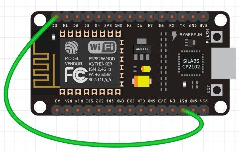
However, when using ESP8266 there is an important step that needs to be done in order to wake up the module. If it is not followed then it will not wake up. We have to make sure that the GPIO16 (D0) of the ESP8266 NodeMCU board is connected with the RST pin.
For ESP8266 NodeMCU, GPIO16 has a ‘wake’ feature attached to it. When the module is powered ON, the RST pin is in a HIGH state but when its state goes to LOW, the board restarts. So in order to wake up the module, the RST pin should be in a LOW state. This is achieved by connecting it to GPIO16. When we configure a deep sleep timer with a timer wake up in ESP8266, the GPIO16 goes to a LOW state whenever the predefined time is finished. This in return causes the development board to awaken. The figure below shows the connection between the two pins.
How to use the Timer Wake Up in ESP8266 using Arduino IDE
We will use the deepSleep() function which is available in the Arduino IDE. The deepSleep() function has a single argument that denotes the sleeping time in microseconds.
We are going to show you a simple demonstration of how to use a timer to wake up the ESP8266 module. The ESP8266 will remain in the active mode for 60 seconds and after that time is over, the ESP8266 will be back in deep sleep mode. It will remain in deep sleep for 60 seconds. After that, it will again wake up and execute the same code.
Open your Arduino IDE and go to File > New to open a new file. Copy the code given below in that file and save it.
void setup() {
  Serial.begin(115200);
  Serial.setTimeout(2000);
  while(!Serial) { }
  Serial.println("I'm awake, but I'm going into deep sleep mode for 60 seconds");
  ESP.deepSleep(6e7);
}

void loop() {
}
Inside the setup() function we will open the serial monitor at a baud rate of 115200. Then we will use ESP.deepSleep() to put the ESP8266 board to sleep. We have specified 6e7us (60 seconds) as the parameter inside the deepSleep() function. This means that after every 60 seconds the module will go to sleep and then wake up.
Demonstration
Choose the correct board and COM port before uploading your code to the board.
Go to Tools > Board and select ESP8266 NodeMCU Module.

Next, go to Tools > Port and select the appropriate port through which your board is connected. Click on the upload button to upload the code into the ESP8266 NodeMCU development board.
Note: Before uploading your code make sure you have connected GPIO16 with RST to wake up your ESP8266 NodeMCU.
After you have uploaded your code to the ESP8266 NodeMCU development board press its RST button.

In your Arduino IDE, open up the serial monitor and you will be able to see the messages after every 60 seconds when the ESP8266 board goes to deep sleep.

ESP8266 External Wake Up
External Wake up in ESP8266 works in a different way. We will use the RST pin connected with a push button as an external wake up. The ESP8266 board will be set to deep sleep for an unlimited amount of time. In order to wake up ESP8266 with an External Wake up we need to set the RST pin to a LOW state that is when the module will restart. Whenever we will press the RST button, the module would wake up. We will need the following components to configure External Wake up in ESP8266 in a very simple example.
Required Components
- ESP 8266 NodeMCU
- One Push button
- One 10k ohm resistor
- Breadboard
- Connecting Wires
Schematic Diagram
Assemble the circuit as shown in the connection diagram below.
As we can see in the above diagram, one terminal of the push-button is connected by RST through the resistor and 3.3V power supply. The other end of the terminal is common ground with the board.
Arduino Sketch ESP8266 External wake up
Open your Arduino IDE and go to File > New to open a new file. Copy the code given below in that file and save it.
void setup() {
Serial.begin(115200);
Serial.setTimeout(2000);
while(!Serial) { }
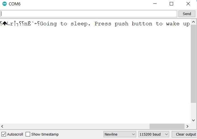
Serial.println("Going to sleep. Press push button to wake up");
ESP.deepSleep(0);
}
void loop() {
}Inside the setup() function we will use ESP.deepSleep() with 0 as an argument inside the function. This will cause the ESP8266 board to go in deep sleep mode for an undefined time.
Demonstration
Choose the correct board and COM port before uploading your code to the board.
Go to Tools > Board and select ESP8266 NodeMCU Module.
Next, go to Tools > Port and select the appropriate port through which your board is connected. Click on the upload button to upload the code into the ESP8266 NodeMCU development board.
After you have uploaded your code to the ESP8266 NodeMCU development board press its RST button.
In your Arduino IDE, open up the serial monitor. Now you will see that the ESP8266 will go to the deep sleep mode. But if you press the push button, it will wake up from deep sleep.
Conclusion
In conclusion, we learned about ESP8266 deep sleep mode and its wake up sources. The wake up sources includes timer wake up and external wake up.
Related tutorials: