In this tutorial, we will discuss the basic introduction and workings of a Power Line Communication or PLC for short. Power Line Communication (PLC) carries data on a conductor that has other simultaneous uses, such as AC electric power transmission or electric power distribution to consumers. The other names of PLC include power-line carrier, power-line digital subscriber line (PDSL), mains communication, power-line telecommunications, or power-line networking (PLN).
Power lines were originally devised to transmit electric power in the frequency range of 50–60 Hz. Initially, the first data transmissions over power lines were done only to protect sections of the power distribution system in case of faults. Power Line Communication was the best way for a fast exchange of information between power plants, substations, and distribution centers. The logic included the fact that power transmission towers are some of the most robust structures ever built. Hence, protection signals could be reliably sent using this signaling network. Moreover, many remote locations were not hooked up to telephone networks. Thus, it was determined that signaling and exchanging information for power system protection and telemetering purposes over existing power lines was the optimal solution.

Types of PLC
- Low Frequency PLC: Mainly used for telecommunication, tele-protection, and tele-monitoring between electrical substations through power lines at high voltages, such as 110 kV, 220 kV, and 400 kV.
- Medium Frequency PLC (> 100 kHz): Narrowband power line communications began soon after electrical power supply became widespread. One natural application of narrowband power line communication is the control and telemetry of electrical equipment such as meters, switches, heaters, and domestic appliances.
- High Frequency PLC (> 1 MHz): Power line communications are also useful in interconnecting home computers, peripherals, and home entertainment devices that have an Ethernet port. Powerline adapter sets plug into power outlets and establish an Ethernet connection using the existing electrical wiring in the home. This allows devices to share data without the inconvenience of running dedicated network cables.
- Ultra High Frequency PLC (> 100 MHz): These systems claim symmetric and full-duplex communication in excess of 1 Gbit/s in each direction. Multiple Wi-Fi channels with simultaneous analog television in the 2.4 and 5.3 GHz unlicensed bands have been demonstrated operating over a single medium-voltage line conductor.
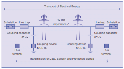
How Power Line Communication Works
The power line carrier was not specifically designed for data transmission and provides a harsh environment for it. Varying impedance, considerable noise, and high levels of frequency-dependent attenuation are the main issues. Over such a complicated line network, the amplitude and phase response may vary very widely with frequency. Moreover, the channel transfer function itself is time-varying since lugging in or switching off devices connected to the network would change the network topology. Home devices often act as noise sources, affecting the signal-to-noise ratio of receivers.
Just like a wireless channel, signal propagation does not take place between transmitter and receiver along a line-of-sight path. As a result, additional echoes must be considered. This echoing occurs because a number of propagation paths exist between the transmitter and the receiver. Reflection of signals often occurs due to the various impedance mismatches in the electric network. Each multi-path would have a certain weight factor attributed to it to account for the reflection and transmission losses. The observation of data at higher frequencies shows that the channel attenuation increases. Hence, the channel might be described as random and time-varying, with a frequency-dependent signal-to-noise ratio (SNR) over the transmission bandwidth.

Noise in Power Lines
Noise in power lines is a significant problem for data transmission. Typical sources of noise are brush motors, fluorescent and halogen lamps, switching power supplies, and dimmer switches. The noise in power lines can be impulsive or frequency-selective in nature. The noise from power lines can be classified into four categories:
- Colored Noise: Relatively low power spectral density, which decreases with frequency. It is considered to be the sum of all low-power noise sources and may be time-varying.
- Narrowband Background Noise: Mainly due to amplitude-modulated sinusoidal signals from broadcast stations in the medium and short wave bands.
- Impulse Noise: Noise that is synchronous with the generator’s actual supply frequency, which usually repeats at multiples of 50/60 Hz. It is of short duration and has a power spectral density that decreases with frequency. It is caused by power supplies.
- Asynchronous Impulse Noise: This is the most detrimental type of noise for data transmission. Its duration varies from a few microseconds to milliseconds. The power spectral density of such impulse noise may be as much as 50 dB above the background noise spectrum. Hence, it is capable of wiping out blocks of data symbols during high data transmission at certain frequencies; it is caused by switching transients in the system network.
Modulation Techniques
Modulation Techniques such as frequency shift keying (FSK), code-division multiple access (CDMA), and orthogonal frequency division multiplexing (OFDM) are appropriate modulation schemes for PLCs. For low-cost, low-data-rate applications, such as power line protection and telemetering, FS is probably a good solution. Frequency-selective fading as experienced by the power line channel severely impairs the capacity of FSK for data rates beyond a few kilobytes per second. A high degree of error control coding would be needed. Combined with the low spectral efficiency of FSK, it would limit the data rate achieved.
For data rates up to 1 Mbps, the CDMA technique may provide an effective solution. The signal of each user is spread using a spreading code at the transmitter. The receiver de-spreads the message using the same code. CDMA provides robustness against narrowband noise and other forms of interference. However, the processing gain must be high to effectively counter interference from other users. While transmitting over power lines at high data rates, the symbol duration is so small that delayed versions of one symbol get smeared over a large number of other symbols. This makes the detection process complicated since it requires complex equalization techniques to counter the inter-symbol interference.
High Data Applications
However, for high-data-rate applications beyond that, OFDM is the technology of choice for PLCs. The serial data passes through a serial-to-parallel converter. It splits data into a number of parallel channels with individual modulators. Each modulator has a different carrier frequency and carries a small portion of the original data rate. This increases the symbol length so that it becomes longer than the longest delay path; this solves the inter-symbol interference problem to a large extent. OFDM also avoids transmitting at frequencies in deep fade. All parallel modulators need to attain a minimum threshold of signal-to-noise ratio; otherwise, the system turns them off. Modulators with a high signal-to-noise ratio carry more bits using the adaptive bit loading technique.
For medium access control of multiple users to the network transmission capacity, a resource sharing strategy is used. Contention-based protocols may cause collisions; hence, they are not suitable, whereas arbitration protocols like Polling, Aloha, and Carrier Sense Multiple Access (CSMA) are more preferable for resource sharing. CSMA/CA listens to the signal level to determine when the channel is idle, and it transmits small data packets to avoid collisions and retransmissions.
Advantages of PLC
- Simplicity: Most private homes do not have dedicated high-speed network cabling installed. The labor costs required to install such wiring are often quite high. Power Line Communication uses an existing electrical network for communication. So the communication service can be provided wherever power outlets exist.
- Flexibility: PLCs are suitable for high, medium, and low voltage supplies. They are useful in internal electrical installations within buildings for various communication applications. If multiple power outlets are available in every room, the home power supply infrastructure presents an excellent network for sharing data among intelligent devices.
Disadvantages of PLC
- Compromised Security: Power Line Communication is not necessarily secure. Many receivers can eavesdrop on the communication.
- Data Attenuation: High-frequency signals face attenuation because power lines behave like a low-pass filter.
- High Costs of Residential Appliances: The cost of a PLC modem is often higher than a phone line modem.
- Noise: Typical sources of noise are brush motors, fluorescent and halogen lamps, switching power supplies, and dimmer switches. The noise in power lines distorts digital and analog signals.
Applications of PLC
The PLC market is expanding dynamically. Advanced energy services include applications such as automatic meter reading, programmable controllers, and demand-supply management. There are several applications of PLC networking in homes: shared internet, printers, files, home control, games, distributed video, remote monitoring, and security.
The Homeplug Powerline Alliance was founded by Cogency, Conexant, Enikia, Panasonic, Intellion, Netgear, RadioShack Co., Sharp, Cisco Systems, Motorola, Texas Instruments, and other partners. It provides a forum for creating open specifications for high-speed home power line networking products and services reaching data rates of 14 Mb/s. The Homeplug standard uses OFDM in burst mode as a physical layer modulation. It uses a combination of sophisticated forward error correction, interleaving, error detection, and automatic repeat requests. The Medium Access Control protocol is CSMA/CA.
The European Home System (EHS) consortium defines a communication protocol between appliances and the central processing unit in homes. It covers several medium types to transmit control data, power, and information. All share the Logical Link Control sublayer.
Powernet aims at developing “plug and play” cognitive broadband over power lines (CBPL). Communications equipment meets the regulatory requirements concerning electromagnetic radiation and can deliver high data rates while using a low transmit power spectral density.
The IEEE BPL Study Group has devised standards for ‘broadband over Power line hardware’, ‘Power Line Communication Equipment Electromagnetic Compatibility Requirements: – Testing and Measurement Methods’, Medium Access Control and Physical Layer Specifications.
References
[1] https://www.researchgate.net/publication/3227750_Power_line_communication_An_overview
[2]https://library.e.abb.com/public/e592d40970c750a8c12571930041e152/50-53%202M633_ENG72dpi.pdf
[3] https://en.wikipedia.org/wiki/Power-line_communication
Conclusion
In conclusion, this tutorial provides an in-depth overview of Power Line Communication. It covers types of PLCs, their workings, noises, and modulation techniques. At last, this tutorial provides the advantages, disadvantages, and applications of Power Line Communication to help us better understand its capabilities and limitations, along with its diverse range of applications. Hopefully, this was helpful in expanding your knowledge of Power Line Communication.
You may also like to read:
- Control Relay Module Remotely with ESP32 Web Server and 220V Lamp
- MB102 Breadboard Power Supply module – How to use it
- ADC0804 ADC Introduction, Pinout, Features, and Examples
- LM4871 Audio Power Amplifier Pinout, Examples and Applications
- Headless Setup of Raspberry Pi without Keyboard and Monitor
- Electronics Engineering Education: Interesting Facts and Benefits
This concludes today’s article. However, if you face any issues or difficulties, let us know in the comment section below.
We will appreciate it if you inform us of suppliers of 2.4 or 5.4 G bps PLC chip.