The LM4871 is a mono bridged audio amplifier with a shutdown feature. It can deliver continuous average power of 3W to 3Ω load. The total harmonic distortion here is 10% provided the supply voltage is 5V. LM4871 has a power shut down mode in which power saving is made by applying to the shutdown pin. The typical value for shut down mode is typically 0.6 µA. LM4871 produces high power exact power audio output. It bypasses the use of a large number of external components. It operates well between the voltages of 2.0-5.5V.
Coupling capacitors, bootstrap capacitors, and snubber circuits are not required to be used for the operation of LM4871. This property makes an LM4871 audio amplifier ideal for its use as portable systems. Generally, stability is an issue at the lowest closed-loop gain but LM4871 is highly unity-gain stable. The gain can be adjusted using external resistors and power shut down protection is also wisely incorporated.
Recommended Components
The following parts are used in this article, along with a generic electronics kit that is handy for building and testing the circuit.
| Component | How it’s used | Buy on Amazon |
|---|---|---|
| LM4871 audio amplifier | The LM4871 mono bridged audio power amplifier this article covers. | Check Price |
| Electronic component assortment kit (1390 pcs) | A handy assortment of resistors, capacitors, LEDs, diodes and transistors for building circuits. | Check Price |
| Digital multimeter (AstroAI) | Measures voltage, current, resistance and checks continuity while you build and debug. | Check Price |
| Breadboard | Solderless base for prototyping the circuit. | Check Price |
| Jumper Wires | Make the connections on the breadboard. | Check Price |
As an Amazon Associate we earn from qualifying purchases. Prices and availability are accurate as of the date/time indicated and are subject to change.
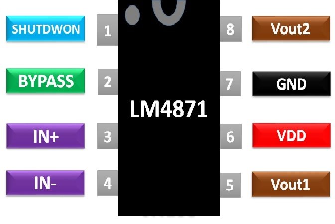
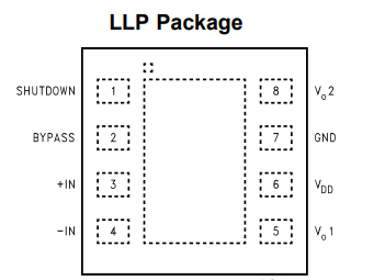
Pinout Diagram LM4871 audio amplifier
The MSOP, small outline and DIP packages come as 8-pin ICs. The pin configuration diagram is given below and the table lists all explanations of all pins with the functionality of each pin.
| PINS | Details |
|---|---|
| 1 (Shutdown) | This pin is for shutdown mode selection |
| 2 (Bypass) | This pin for connecting bypass pin capacitor |
| 3 (Non-Inverting Input +IN) | This pin is for applying inverting input voltage |
| 4 (Inverting Input -IN) | This pin is for applying non-inverting input voltage |
| 5 (Output Voltage ) | This pin is for obtaining output voltage-terminal one |
| 6 ( VDD) | This pin is for applying fixed biasing voltage |
| 7 (Ground GND) | This pin is for connecting ground |
| 8 (Output Voltage ) | This pin is for obtaining output voltage-terminal two |
LM4871 Features and Specifications
LM4871 avoids the usage of output coupling capacitors, bootstrap capacitors and snubber circuits. It ensures unity-gain stability. It is available as LLP, MSOP, SO and DIP packaging. The gain can simply be adjusted externally. The pins have compatibility with LM 4861. The operational features of LM4871 are shown as:
| Parameters | LM4871 |
|---|---|
| Supply Voltage (V) | 5.5 |
| Quiescent Power Supply Current (mA) | 10 |
| Shut Down current (µA) | 2 |
| Output Offset Voltage (mV) | 50 |
| Output Power (W) | 2.38 |
| Total Harmonic Distortion + Noise (%) | 0.13/0.25 |
| Power Supply Rejection Ratio (dB) | 60 |
| Supply Temperature (°C) | -65 to +150 |
| Junction Temperature (°C) | 150 |
| Soldering Info. SOP Package- Vapor Phase (60s) (°C) | 215 |
| Soldering Info. SOP Package- Infrared (15s) (°C) | 220 |
Where and How to Use LM4871 Audio Amplifier
To use this audio amplifier in any electronics circuit, you should have a clear understanding of all pins. Let’s start with an example using an Audio power amplifier. Input resistance Ri is connected to pin 4 where the audio input signal is fed through a capacitor Ci in series with. This resistance-capacitor combination in actual forms a high pass filter with cut-off frequency given by f= 1/2πRiCi. It ensures the blocking of DC voltages. Rf and Ri determine the closed loop gain. Rf is connected between pin 4 and 5. Cs is connected to pin no. 6 and supply voltage in such a way that it provides supply filtering. A capacitor CB is connected to bypass pin no 2 to achieve half-supply filtering. For power shutdown mode, Iq equal to 0.6 µA is achieved when the supply voltage is applied at shut down pin no. 1. Pin no. 7 is grounded while the audio output is obtained between pins 5 and 8. A typical audio power amplifier Example is shown below.
LM4871 Example
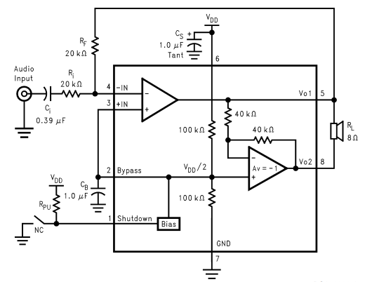
In this example, one amplifier output acts as an input to another audio power amplifier. In this circuit, both amplifiers generate an output having same magnitude but `180 degrees out of phase with each other.
Applications
The real-life applications of LM4871 are:- Portable computers
- Desktop computers
- Low voltage audio systems
- Guitar amplifier
- Keyboard amplifier
- Talking toys
- Hi-Fi devices
- Radio wave transmitter
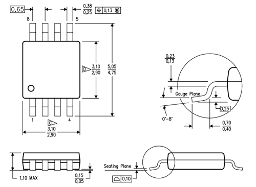
2D Diagram Audio Power Amplifier IC
To make PCB design, you might also need to consult the 2D dimension diagram of IC. This picture shows 2D dimension diagram from the datasheet for the PDSO package. You can download the datasheet given at the end for more details.