How to design power factor using Arduino? How to measure power factor using Arduino Uno R3 ? In this project, I have designed a power factor meter using Arduino Uno R3. In last two articles, I have posted project on how to measure alternating voltage using Arduino and how to measure alternating current using Arduino? As you know power factor is used to calculate ac power consumed by the load. It is also used to design energy meter. So by designing power factor meter we can design digital ac watt meter very easily. Because we know that ac power or watt consumed by the load is equal to product of ac voltage, ac current and power factor. we already seed how to measure ac voltage and ac current using Arduino and if we able to design power factor meter using Arduino, then we can easily design digital ac watt meter using Arduino. 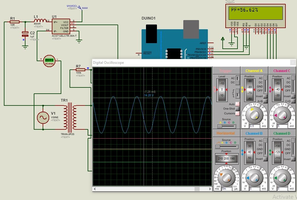
You may also interested in following articles:
- Power factor measurement using pic microcontroller
- power factor controller using pic microcontroller
- ac power measurement using pic microcontroller
- three phase ac power measurement using pic microcontroller
Recommended Components
The following components are used in this project or are helpful for building it with the Arduino.
| Component | How it’s used in this project | Buy on Amazon |
|---|---|---|
| Arduino Uno R3 | The main controller board that computes and displays the power factor. | Check Price |
| 16×2 LCD (parallel) | Displays the measured power factor value to the user. | Check Price |
| Breadboard | Solderless board to build and prototype the circuit without soldering. | Check Price |
| Jumper Wires | Used to make the connections between the Arduino, breadboard, and LCD. | Check Price |
As an Amazon Associate we earn from qualifying purchases. Prices and availability are accurate as of the date/time indicated and are subject to change.
Main components for power factor measurement using Arduino
Followings are the main components used in this project.
Arduino
Arduino is a heart of this project. Arduino measured the time difference between current wave form and voltage wave forms. The time difference between current wave form and voltage wave form is basically a phase difference between two waves. This phase difference is used to calculate power factor with the help cos function that is cos(phase difference).Current sensor
I have used acs712 current sensor in this project. Output wave of current sensor is fed to Arduino analog channel. Current sensor can also use to measure current and to measure current wave form of load current.voltage sensor
In this project, I have used step down transformer to step down voltage from 220 volt AC to 12 Volt AC and further this voltage is step down using voltage divider circuit. Because Arduino can never measure voltage more than 5 volt directly.Lcd display
Lcd is interfaced with Arduino to display measured voltage on lcd. if you don’t know how to use LCD with Arduino, you can check this tutorial on lcd interfacing with Arduino.So these are the main components used for power factor measurement using Arduino and how to design power factor meter using Arduino development board. So now let’s check the circuit diagram of Arduino based power factor meter. I have explained all the main components used to design arduino based power factor meter above.
Circuit diagram Arduino based power factor meter design
Circuit diagram of Arduino based power factor meter is given below:
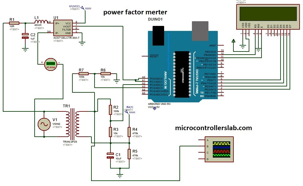
Circuit Working
Circuit diagram of power factor meter using Arduino consists of current sensor and voltage sensor circuits. Current sensor circuit use acs712 current sensor and voltage sensor circuit consists of step down transformer and voltage divider circuit. Arduino measures the power factor by comparing the time difference between current wave form and voltage wave form. After calculating power factor, Arduino displays it on LCD.
Vide Simulation
Video simulation of Arduino based power factor meter is given below:
Hello, I am currently trying to develop a project for energy measurement. I am using a transformer of voltage 127-12 V and a transformer of current 30A / 15mA, I am already measuring voltage and current, I would like to know if you can advise me for the question of the power factor.
Send me for power factor metering system using arduino abstract
Can I get a code for this project
How can we get the code for this project????
does any one have code for powrrfactor measurement
Nice
please share the code