In this article, we will see different types of data transfer instructions supported by the 8086 microprocessor. We will see the function of each instruction with the help of an assembly language program. These are the instructions that transfer the data from source to destination. They include:
- MOV, PUSH, POP, XCHG, XLAT transfer bytes, or words.
- IN, OUT transfer input and output ports.
- LEA, LDS, LES transfer addresses.
- LAHF, SAHF, PUSHF, POPF transfer flag registers.
In the last tutorial, we have discussed 8086 addressing modes.
8086 Microprocessor Data Transfer Instructions
All of these instructions are discussed in detail.

1. MOV Instruction
The MOV instruction copies a byte or a word from source to destination. Both operands should be of same type either byte or a word. The syntax of this instruction is:
MOV Destination, SourceThe destination operand can be any register or a memory location whereas the source operand can be a register, memory address, or a constant/immediate. The 8086 MOV instruction supports the following operands:
| Source | Destination | Example |
| Reg | Reg | MOV AX, BL |
| Memory Address | Reg | MOV CX, [2341] |
| Reg | Memory Address | MOV [7012], AH |
| Immediate | Reg | MOV AL, 21C |
| Immediate | Memory Address | MOV [2310], 37B2 |
| Segment Register | Reg | MOV AX, DS |
| Reg | Segment Register | MOV CS, CX |
The instruction MOV mem, mem is illegal. It is not possible to transfer data directly from one memory location to another. Therefore, both source and destination operands cannot be memory address. The MOV instruction does not affect any value in the flag register.
Example Assembly Code
Consider an example to understand the behavior of MOV instruction. In the code given below, a and b are the variables. DB is used for storing byte and DW is used for storing a word (2 bytes).
ORG 100h
MOV AX, a           ;Set AX to 'a' variable
MOV CX, 712h        ;Set CX to 712h
MOV DS, CX          ;Copies value of CX into DS
MOV SI, 25          ;Set SI to 0019 (decimal value of 25)
MOV [105], 6Ah      ;Sets memory address 02712:0069 to 6Ah
MOV 25[BP][SI], AX  ;PA=SS(Shifted left)+a+BP+SI
                    ;Copy data from AX to physical address(PA)
MOV DL, [BX]+6      ;Load data from PA=DS(Shifted left)+BX+6 to DL
RET                 ;stops the program

a DW 5C21h
Output:
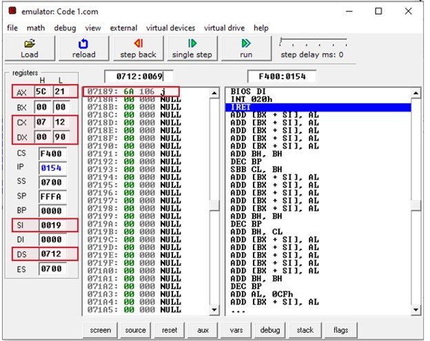
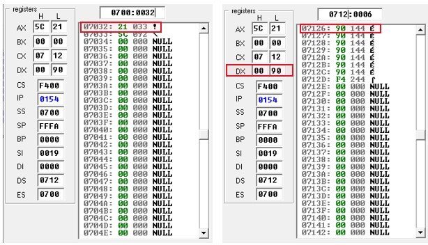
The memory block has four columns. First column is of offset address. Second and third column shows the hexadecimal value and decimal value stored in that offset address. The last column indicates the ASCII character value. The 6th instruction in the code stores the hexadecimal value 6Ah at Physical address 07189 (07120h + 0069h). In the 7th instruction, the value of AX is stored at physical address 07032 (07000h+0032h). The instruction MOV DL, [BX]+6 loads the value from memory location 07126 into DX shown in figure (3).
2. 8086 PUSH Instruction
The PUSH instruction pushes the data in the stack. The format of PUSH instruction is:
PUSH SourceIt decrements the stack pointer by two and then stores the data from the source operand at the position of the stack pointer. The source operand can be a general-purpose register, segment register or a memory address but it should be a word.
PUSH Assembly Code
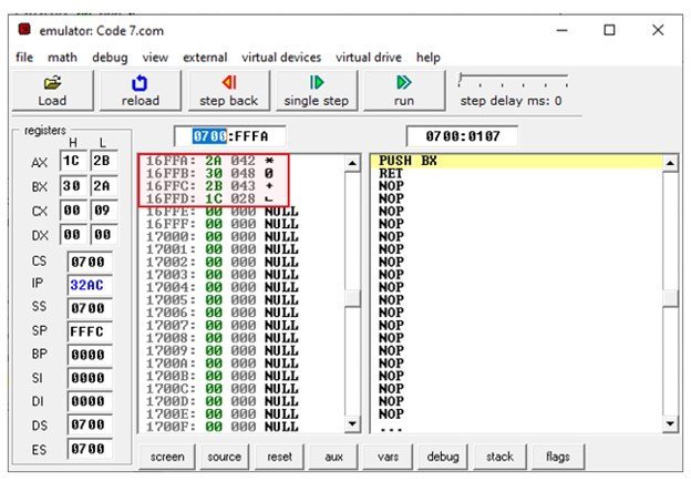
The PUSH instruction decrements the SP by 2. You can see in the output the SP=FFFC which decrements by 2 becomes FFFA. The data of AX is pushed to memory location DS: FFFA which is 16FFA in this example.
ORG 100h
MOV AX, 1C2Bh       ;Set AX to 1C2B
PUSH AX             ;Set SP=SP-2
                    ;Push AX data to stack location DS:SP
MOV BX, 302Ah       ;Set BX to 302A
PUSH BX             ;SP=SP-2
                    ;Push BX data to stack location DS:SP
RET                 ;stops the program
Output
3. 8086 POP Instruction
It is opposite to the POP instruction. The POP instruction loads the word from the stack pointed by SP and then increments the SP by 2. The format for this instruction is:
POP destinationThe destination operand can be a general-purpose register, segment register, or memory address. The POP instruction does not support CS as a destination operation.
POP Example Assembly Code
ORG 100h
MOV AX, 1C2Bh       ;Set AX to 1C2B
PUSH AX             ;Set SP=SP-2
                    ;Push AX data to stack location DS:SP
MOV BX, 302Ah       ;Set BX to 302A
PUSH BX             ;SP=SP-2
                    ;Push BX data to stack location DS:SP
POP CX              ;Load the last value stored at stack into CX which is BX
                    ;increment SPby 2 i.e., SP=SP+2
POP [12H]           ;Load the value from location of SP to memory address DS:0012H
                    ;increment SP by 2
RET                 ;stops the program
4. Operand Exchange Instruction (XCHG)
The XCHG instruction exchanges the contents of the source and destination. Both operands should be of the same type either word (16 bits) or a byte (8 bits). It does not support segment registers. The direct exchange of data between memory locations is illegal. Both operands should be a general-purpose register. The syntax of instructions is:
XCHG Destination, SourceFor example
- XCHG AX, BX exchanges words
- XCHG AL, BL exchanges bytes.
XCHG CL, 25[BX] exchanges bytes of CL with bytes stored in memory location DS:25+BX.
XCHG CS, AX is illegal.
Example Assembly Code
ORG 100h
MOV AX, a           ;Set AX to 'a' variable
MOV CX, b           ;Set CX to 'b' variable
XCHG AX, CX         ;Exchange words of AX and CX
XCHG AH, CL         ;Exchange bytes of AH and CL
RET                 ;stops the program

a DW 5C21h
b DW 3D05h
Output

The code given above first sets AX to 5C21 and CX to 3D05.
| AX | 5C21 | CX | 3D05 |
| AH | 5C | CH | 3D |
| AL | 21 | CL | 05 |
After execution of fourth instruction XCHG AX, CX, the contents of AX and CX are exchanged. AX becomes CX and CX becomes AX.
| AX | 3D05 | CX | 5C21 |
| AH | 3D | CH | 5C |
| AL | 05 | CL | 21 |
Then XCHG AH, CL exchanges the most significant bits of AH with lower bits of CL. The final output becomes:
| AX | 3D05 | CX | 5C21 |
| AH | 21 | CH | 5C |
| AL | 05 | CL | 3D |
Just like MOV instruction, the XCHG instruction does not modify the contents of flag register. The
5. XLAT Instruction
The XLAT instruction takes no operands. It is used in lookup tables. The BX register contains the offset address of the lookup table. The AL register has a byte number. The XLAT instruction takes the byte number from AL and load the contents of address DS: BX+AL into AL register. The syntax for this instruction is:
XLAT
or
XLAT Table_Name
First, you’ll have to store the starting offset address of table into BX register which is done by:
MOV BX, OFFSET Table_NameExample Assembly Code
Now, consider an example which takes a variable a in a range 1 to 15 and display it as a hexadecimal digit. We have taken a=13.
ORG 100h
.MODEL SMALL
.DATA
TABLE DB '0123456789ABCDEF'
a     DB      13
.code
MOV AL,a            ;AL stores the byte number
MOV BX,OFFSET TABLE ;Sets BX to offset of starting address of the table
XLAT                ;Sets AL to the hexa decimal value of var a
MOV DL,AL
MOV AH,02H          ;Displays the charachter stored in DL
INT 21H
MOV AH,4CH
INT 21H
RET                 ;stops the program
Output
8086 I/O Port Data Transfer Instructions
These two instructions are supported by 8086 microprocessor to take directly transfer data between GPIO ports.
IN Instruction
The IN instruction takes the input from the port and transfers that data into the register. Thus, data transfer takes place between register and I/O device. The syntax of IN instruction is:
IN Reg, Port AddressThe range of port addresses is from 000H to FFFFH.
IN AX, 29HIf you want to access a port number over 255 then first load the port address into DX and then use IN instruction.
MOV DX, FA32H
IN AX, DX
OUT Instruction
The OUT instruction outputs the data of register on to a port specified in the instruction. The syntax of this instruction is:
OUT Port Address, RegisterExample
OUT 26H, ALIf you want to use port address over 255, then store this port address to DX and then execute OUT instruction
MOV DX, 456DH
OUT DX, AX
LEA Instruction
The LEA stands for load Effective address. As the name implies, it takes the data from the source and copies it to the destination operand. The destination is always a register whereas the source can be an offset address of a variable or a memory location. Both MOV and LEA instructions copy data from source to destination but the difference between them is LEA copies only offset address or a memory address to destination register. The syntax of LEA instruction is:
LEA Reg, SourceFor example:
- LEA AX, [BX] Stores the offset address of BX into AX.
- LEA CX, var_1 Stores the address of var_1 into CX register
- LEA BX, [BP][SI] Loads effective address = BP+SI into BX register
Example Assembly Code
ORG 100h
.MODEL SMALL
.DATA
VAR DB 23h
.code
MOV AX,@DATA  ;Sets AX equal to the starting address of data segment
MOV DS,AX     ;Copy AX to DS
LEA DX,VAR    ;Loads the address of VAR
RET           ;stops the program
Output
In this example, you can see in the memory block, the offset address of variable VAR is 0102h which is stored in DX after execution of LEA instruction.

LDS Instruction
The LDS instruction stores four consecutive memory locations into a specified destination register and a DS register. The format of LDS instruction is:
LDS Reg, Memory AddressThe word from first two memory locations is loaded into a register and the word from the next two memory locations gets stored to DS register.
Example Assembly Code
ORG 100h
.MODEL SMALL
.DATA
VAR DB 23h
.code
LDS AX,VAR
RET
Output

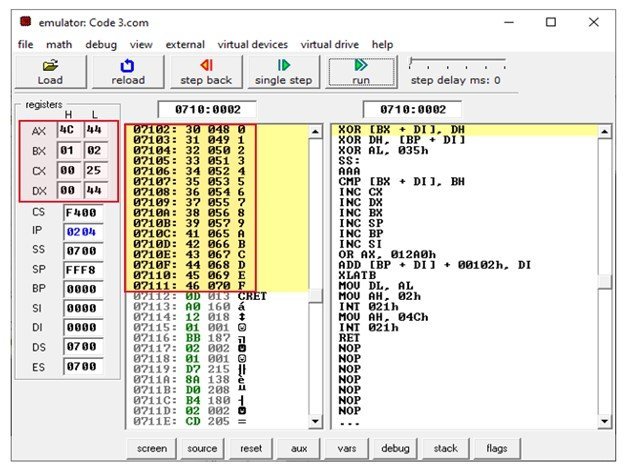
You can observe from the output that the address of variable var is 07012. The words from 07102h, 07103h locations gets stored into AL and AH. The contents of other two memory addresses 07104h and 07105h are loaded into DS.
8086 LES Instruction
This instruction is almost similar to the LDS instruction. It loads data from first two memory locations to a specified register. The data of the next two memory location goes to ES register. The syntax of LES instruction is:
LES Reg, Memory AddressExample Assembly Code
ORG 100h
.MODEL SMALL
.DATA
NUM DB 5Ch
.code
LES SI,NUM
MOV AX,0710H
MOV DS,AX
LES BX,[8H]
RET
Output:

The memory address of Num variable is 7102h. The instruction “LES SI, Num” sets SI to C45C and ES to 0236. The next instruction “LES BX, [8H]” sets BX to 0710 and ES to D88E.
Other 8086 Data Movement Instructions
11. LAHF
The LAHF instruction loads the lower 8 bits of the flag register into AH register. The lower eight bits of flag register includes SF, ZF, AF, PF and CF flags. It does not require any operand.
12. SAHF
The SAHF instruction stores the 8-bit data of AH register into the lower 8 bits of the flag register. It has no operands.
13. PUSHF
It pushes the contents of flag register onto the top of stack. The PUSHF instruction decrements the stack pointer by two and then store the data of flag register at location pointed by stack pointer (SP).
14. POPF
It pops the data from the first two memory locations pointed by stack pointer into the flag register and then increment SP by 2. The POPF instruction has no operands.