Almost all modern microcontrollers come with programmable general purpose timer modules. One of the important applications of GPTM is frequency measurement of analog and digital signals. In this tutorial, we will learn to measure the frequency using TM4C123 Timers in input edge time capture mode. In the last tutorial, we have learned to measure pulse duration or pulse width using the TM4C123 timer in input-edge time mode. We will use the same C code to measure frequency except few changes will be made in the frequency measurement function.
Pre-requisites:
- How to Download and Install Keil uVision for ARM and 8051
- Getting started with Keil uVision: Write your first Program for Tiva LaunchPad
How to Measure Frequency of Analog and Digital Signals?
Timer modules of TM4C123 microcontroller can be used to measure the frequency of either analog and digital signals.
Analog Signal Frequency
For frequency measurement of an analog signal, we will need an external circuit which converts an analog signal into digital signal. The simplest converter circuit can be an operational amplifier used in a comparator configuration mode. But if the analog signal also has a negative amplitude, we should add a DC voltage offset to convert a negative side of the signal into positive side.
Digital Signal Frequency
On the contrary, the frequency of a digital signal can be measured directly using TM4C123 MCU timers given that the amplitude of a digital signal is less than 5 volts. Because the input edge capture GPIO pins of timers can withstand a maximum of 5 volt. Moreover, each GPIO pin takes the voltage value between 3.3 to 5 volts as an active high signal and voltage value less than 3 volts as an active low signal. If the voltage amplitude of a digital signal is greater than the logic level of TM4C123 microcontroller, we should first reduce the amplitude using any voltage level shifter IC.
In short, we can measure the frequency of both analog and digital signals using TM4C123 Timers after performing appropriate signal conditioning.
Measure Frequency using TM4C123 Timers in input-edge Capture Mode
Frequency of any digital signal can be measured with the help of time period of signal.Because timer period and frequency are inversely proportional to each other. The time period of digital signal can be measured by measuring the time between two consecutive rising edges or falling edges of digital signal.
Now let’s take an example to understand this. Figure below shows the digital signal.
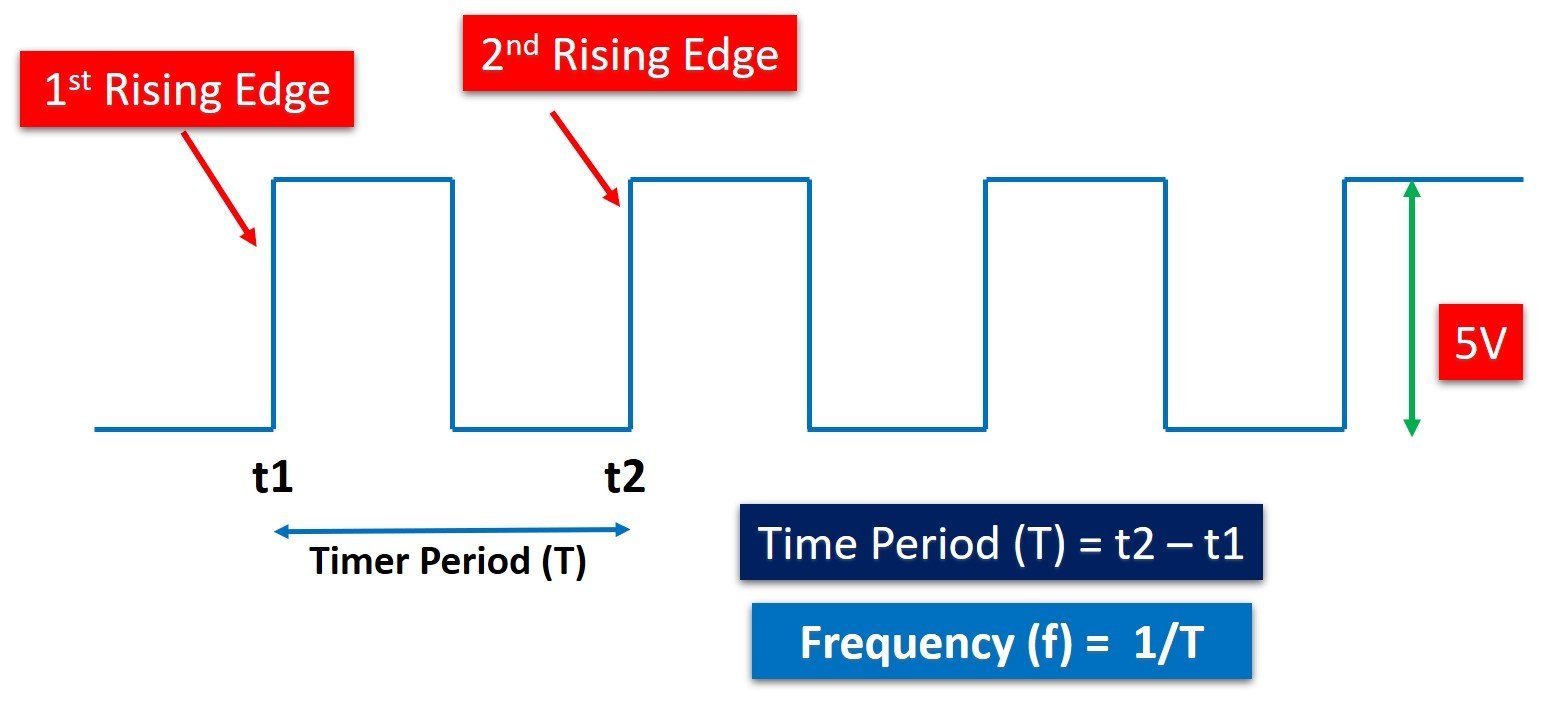
The rising edge of any digital signal is an edge where the transition of the signal occurs from an active low level to an active high level. Furthermore, the time period is the time between two consecutive rising edges or falling edges. As shown in this figure, the first rising edge occurs at time t1 and the second consecutive rising edge occurs at time t2. The time elapsed between t1 and t2 is equal to the time period (T) of a digital signal. Hence, we can calculate frequency by taking the inverse of the timer period that is f = (1 / T).
Caculate Frequency from Timer Period
Time period of a digital signal can be measured by using the TM4C123 timer in input-edge capture mode. The timers of Tiva C microcontrollerr can be configured to capture events on GPIO pins such as rising, falling or both edges. In this case, we can configure the timer to capture two consecutive rising edges and time measured between two consecutive will be the timer period of signal.
Configuring TM4C123 Timer to capture Rising Edges
In the last tutorial, we have seen how to configure TM4C123 timers in input-edge capture mode to measure pulse duration. Hence, the steps to configure and initialize time in input-edge capture mode are the same as the last tutorial. The only difference is that to measure time period or frequency, we will configure capture event on the GPIO pin as a rising edge only.
Clearing Bit 2 and 3 (TAEVENT) of the GPTMCTL control register configures the positive edges as a capture event for Timer0A.
TIMER0->CTL &= ~(1<<3)|~(1<<2); /* capture rising edges on PB6 pin */We use Timer block 0 and sub timer A in this tutorial. This void Timer0ACapture_init(void) function configures the Timer0A in input edge capture mode by selecting input-edge time mode. PB6 pin of PORTB is used as an external event capture pin.
* Configure Timer0A in input-edge time capcture mode */
void Timer0ACapture_init(void)
{
    SYSCTL->RCGCTIMER |= 1;     /* enable clock to Timer Block 0 */
    SYSCTL->RCGCGPIO |= 2;      /* enable clock to PORTB */

    GPIOB->DIR &= ~(1<<6);        /* make PB6 an input pin */
    GPIOB->DEN |= (1<<6);         /* make PB6 as digital pin */
    GPIOB->AFSEL |= (1<<6);       /* use PB6 alternate function */
    GPIOB->PCTL &= ~0x0F000000;  /* configure PB6 for T0CCP0 */
    GPIOB->PCTL |= 0x07000000;

    TIMER0->CTL &= ~(1<<0);          /* disable timer0A during setup */
    TIMER0->CFG = 4;            /* Timer0A in 16-bit timer mode */
    TIMER0->TAMR = 0x17;        /* Timer0A enable up-count and capture mode */
    TIMER0->CTL &= ~(1<<3)|~(1<<2);   /* capture rising edges on PB6 pin */
    TIMER0->CTL |= (1<<0);           /* enable Timer0A */
}
Measure_TimerPeriod() routine measures and returns the time period of digital signal by capturing time between two consecutive rising edges.
/* This function captures two onsecutive rising edges of a periodic signal  */
/* from Timer Block 0 Timer A and returns the time difference */
int Measure_TimerPeriod(void)
{
    int risingEdge, fallingEdge;
	  /* detect first rising edge */
    TIMER0->ICR = 4;            /* clear timer0A capture flag */
    while((TIMER0->RIS & (1<<2)) == 0) ;    /* wait till first positive edge captured */
    risingEdge = TIMER0->TAR;     /* save the timestamp */
		/* detect second rising edge */
    TIMER0->ICR = 4;            /* clear timer0A capture flag */
    while((TIMER0->RIS & (1<<2)) == 0) ;    /* wait till second positive edge captured*/
    fallingEdge = TIMER0->TAR;     /* save the timestamp */
		return (fallingEdge - risingEdge) & 0x00FFFFFF; /* return the time difference which is time period */
}
The time period value returned by this function is in terms of the number of clock cycles. To convert this value into time format, divide it by the operating frequency of the timer clock.
timer_period_ms = (time_period * 62.5)/1000000; /* convert to time */Once we get the time period, we can easily get signal frequency by taking inverse of time period.
frequency = 1 / timer_period_ms ; /* convert to frequency */Finally, this line prints the value of frequency on a serial monitor through the UART5 module of TM4C123 microcontroller.
sprintf(mesg, "\r\nPulse width = %f ms", frequency); /* convert float to string */
printstring(mesg); /* print frequency on serial monitor*/
We will use a USB to serial converter to connect UART5 pins of the Tiva C launchpad with the computer. To see the output message on the computer, we can use any virtual terminal such as putty, hyperterminal and serial monitor window of Arduino.
If you don’t know how to use UART module of TM4C123 Tiva Launchpad to transfer data to computer, you should read this article:
Frequency Measurement Code TM4C123 Tiva Launchpad
/* This example code can measure the time period and frequency of digital signal */
/* Timer block 0 and sub timer A is configured in capture to capture to consecutive rising edges */

/*header files for TM4C123 device and sprintf library */
#include "TM4C123GH6PM.h"
#include <stdio.h>

/*Function prototype for Timer0A and UART module initialization */

int  Measure_TimerPeriod(void);
void Timer0ACapture_init(void);
void Delay(unsigned long counter);
void UART5_init(void);
void UART5_Transmitter(unsigned char data);
void printstring(char *str);

/* global variables to store and display pulse width or duration */
unsigned int time_period;
char mesg[12];

/* main code to take pulse duration measurement and send data to UART terminal */
float frequency;
float timer_period_ms;
int main(void)
{
	 Timer0ACapture_init();
	 UART5_init();
	while(1)
	{
		  time_period = Measure_TimerPeriod(); // call function to take time period sample
		  timer_period_ms = (time_period * 62.5)/1000000; /* convert to time */
		  frequency  = 1000 / timer_period_ms ;  /* convert to frequency */
		  sprintf(mesg, "\r\nFrequency = %f Hz", frequency); /* convert float to string */
			printstring(mesg); /* print frequency on serial monitor*/
      Delay(1000);
	}

}

/* Configure Timer0A in input-edge time capcture mode */
void Timer0ACapture_init(void)
{
    SYSCTL->RCGCTIMER |= 1;     /* enable clock to Timer Block 0 */
    SYSCTL->RCGCGPIO |= 2;      /* enable clock to PORTB */

    GPIOB->DIR &= ~(1<<6);        /* make PB6 an input pin */
    GPIOB->DEN |= (1<<6);         /* make PB6 as digital pin */
    GPIOB->AFSEL |= (1<<6);       /* use PB6 alternate function */
    GPIOB->PCTL &= ~0x0F000000;  /* configure PB6 for T0CCP0 */
    GPIOB->PCTL |= 0x07000000;

    TIMER0->CTL &= ~(1<<0);          /* disable timer0A during setup */
    TIMER0->CFG = 4;            /* Timer0A in 16-bit timer mode */
    TIMER0->TAMR = 0x17;        /* Timer0A enable up-count and capture mode */
    TIMER0->CTL &= ~(1<<3)|~(1<<2);   /* capture rising edges on PB6 pin */
    TIMER0->CTL |= (1<<0);           /* enable Timer0A */
}

/* This function captures two onsecutive rising edges of a periodic signal  */
/* from Timer Block 0 Timer A and returns the time difference */
int Measure_TimerPeriod(void)
{
    int risingEdge, fallingEdge;
	  /* detect first rising edge */
    TIMER0->ICR = 4;            /* clear timer0A capture flag */
    while((TIMER0->RIS & (1<<2)) == 0) ;    /* wait till first positive edge captured */
    risingEdge = TIMER0->TAR;     /* save the timestamp */
		/* detect second rising edge */
    TIMER0->ICR = 4;            /* clear timer0A capture flag */
    while((TIMER0->RIS & (1<<2)) == 0) ;    /* wait till second positive edge captured*/
    fallingEdge = TIMER0->TAR;     /* save the timestamp */
		return (fallingEdge - risingEdge) & 0x00FFFFFF; /* return the time difference which is time period */
}
void UART5_init(void)
{
	  SYSCTL->RCGCUART |= 0x20;  /* enable clock to UART5 */
    SYSCTL->RCGCGPIO |= 0x10;  /* enable clock to PORTE for PE4/Rx and RE5/Tx */
    Delay(1);
    /* UART0 initialization */
    UART5->CTL = 0;         /* UART5 module disbable */
    UART5->IBRD = 104;      /* for 9600 baud rate, integer = 104 */
    UART5->FBRD = 11;       /* for 9600 baud rate, fractional = 11*/
    UART5->CC = 0;          /*select system clock*/
    UART5->LCRH = 0x60;     /* data lenght 8-bit, not parity bit, no FIFO */
    UART5->CTL = 0x301;     /* Enable UART5 module, Rx and Tx */

    /* UART5 TX5 and RX5 use PE4 and PE5. Configure them digital and enable alternate function */
    GPIOE->DEN = 0x30;      /* set PE4 and PE5 as digital */
    GPIOE->AFSEL = 0x30;    /* Use PE4,PE5 alternate function */
    GPIOE->AMSEL = 0;    /* Turn off analg function*/
    GPIOE->PCTL = 0x00110000;     /* configure PE4 and PE5 for UART */
}
void UART5_Transmitter(unsigned char data)
{
    while((UART5->FR & (1<<5)) != 0); /* wait until Tx buffer not full */
    UART5->DR = data;                  /* before giving it another byte */
}

void printstring(char *str)
{
  while(*str)
	{
		UART5_Transmitter(*(str++));
	}
}
void Delay(unsigned long counter)
{
	unsigned long i = 0;

	for(i=0; i< counter*1000; i++);
}
/* This function is called by the startup assembly code to perform system specific initialization tasks. */
void SystemInit(void)
{
    SCB->CPACR |= 0x00F00000;
}
Demo
To demonstrate the working of the above given frequency measurement code, we will connect a 490Hz frequency signal to PB6 pin (Timer0A capture pin) of TM4C123 Tiva launchpad. We use an Arduino Uno to generate 490Hz frequency digital signal. Because the default frequency of Arduino PWM signal is 490Hz. This code of Arduino generates digital signal and output appears on pin D9 of Arduino.
int ledPin = 9;      // LED connected to digital pin 9
int val = 0;         // variable to store the read value

void setup() {
  pinMode(ledPin, OUTPUT);  // sets the pin as output

  analogWrite(ledPin, 127); // analogRead values go from 0 to 1023, analogWrite values from 0 to 255

}

void loop() {

}
Connection Diagram
Now make the connection between Arduino, TM4C123 Tiva Launchpad and USB to serial converter according to this schematic.
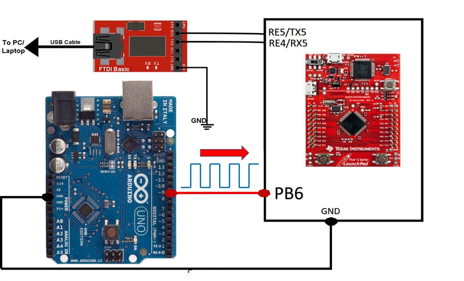
After that upload code to Arduino using Arduino IDE and also TM4C123 using Keil uvision.
Open COM pin to which USB to serial converter is connected. Select the COM pin from the Arduino IDE tool section. Afterwards, open the Arduino serial monitor. After that press the reset button on TM4C123 Tiva Launchpad, you will get frequency measurement output on the serial monitor.

As you can see the measured frequency is almost equal to 490Hz with an error of only 0.001%.
Video Demo
Summary
In conclusion, programmable general-purpose timer modules are essential components in modern microcontrollers, offering versatile applications like frequency measurement for both analog and digital signals. This tutorial builds upon the previous one, where we learned to measure pulse width using the TM4C123 timer in input edge time mode. By making minor adjustments to the pulse width measurement code, we can now effectively measure signal frequency, demonstrating the flexibility and power of TM4C123 Timers in handling different signal analysis tasks.
Other TM4C123 Tutorials:
- GPIO Interrupts TM4C123 Tiva Launchpad
- UART Interrupt TM4C123G
- Systick Timer Interrupt Programming TM4C123
- ADC Interrupt Programming TM4C123 Microcontroller
Related Tutorials:
Hi,
Very Useful Material.
Pl can you share the code for the Frequency & Duty cycle Measurement using Timer Interrupt instead of Polling Method.
Thanks in advance.
with regards,
Ravi